
10.2: Matching Networks
- Page ID
- 41324

Matching networks are constructed using lossless elements such as lumped capacitors, lumped inductors and transmission lines and so have, ideally, no loss and introduce no additional noise. This section discusses matching objectives and the types of matching networks.
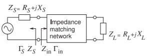
Figure \(\PageIndex{1}\): A source with Thevenin equivalent impedance \(Z_{S}\) and load with impedance \(Z_{L}\) interfaced by a matching network presenting an impedance \(Z_{\text{in}}\) to the source.
10.2.1 Matching for Zero Reflection or for Maximum Power Transfer
With RF circuits the aim of matching is to achieve maximum power transfer. With reference to Figure \(\PageIndex{1}\) the condition for maximum power transfer is \(Z_{\text{in}} = Z_{S}^{\ast}\) which is equivalent to Γin = Γ∗ S. The proof is as follows:
\[\label{eq:1}\Gamma_{\text{in}}=\left(\frac{Z_{\text{in}}-Z_{\text{REF}}}{Z_{\text{in}}+Z_{\text{REF}}}\right) \]
and for maximum power transfer \(Z_{\text{in}} = Z_{S}^{\ast}\), so
\[\begin{align}\Gamma_{\text{in}}^{\ast}&=\frac{Z_{\text{in}}-Z_{\text{REF}}}{Z_{\text{in}}+Z_{\text{REF}}}=\left(\frac{Z_{S}^{\ast}-Z_{\text{REF}}}{Z_{S}^{\ast}+Z_{\text{REF}}}\right)^{\ast} =\frac{(Z_{S}^{\ast}-Z_{0})^{\ast}}{(Z_{S}^{\ast}+Z_{0})^{\ast}} \nonumber \\ \label{eq:2} &=\frac{(Z_{S}^{\ast})^{\ast}-Z_{\text{REF}}^{\ast}}{(Z_{S}^{\ast})^{\ast}+Z_{\text{REF}}^{\ast}}=\frac{Z_{S}-Z_{\text{REF}}^{\ast}}{Z_{S}+Z_{\text{REF}}^{\ast}}=\Gamma_{S} \end{align} \]
If \(Z_{\text{REF}}\) is real, \(Z_{\text{REF}}^{\ast} = Z_{\text{REF}}\) and then the condition for maximum power transfer is
\[\label{eq:3}\Gamma_{\text{in}}^{\ast}=\frac{Z_{S}-Z_{\text{REF}}}{Z_{S}+Z_{\text{REF}}}=\Gamma_{S} \]
Thus, provided that \(Z_{\text{REF}}\) is real, the condition for maximum power transfer in terms of reflection coefficients is \(\Gamma_{\text{in}}^{\ast} =\Gamma_{S}\) or \(\Gamma_{\text{in}} =\Gamma_{S}^{\ast}\).
10.2.2 Types of Matching Networks
Up to a few gigahertz, lumped inductors and capacitors can be used in matching networks. Above a few gigahertz parasitics result in selfresonance. Lumped elements are also lossy. Segments of transmission lines are also used in matching networks as the loss of a transmission line component is always much less than the loss of a lumped inductor. However the length of a transmission line segement is up to \(\lambda /4\) which is far too large to fit in consumer wireless products operating below a few gigahertz. An impedance matching network may consist of
- Lumped elements only. These are the smallest networks, but have the most stringent limit on the maximum frequency of operation. The relatively high resistive loss of an inductor is the main limiting factor limiting performance. The self resonant frequency of an inductor limits operation to low microwave frequencies.
- Distributed elements (microstrip or other transmission line circuits) only. These have excellent performance, but their size restricts their use in systems to above a few gigahertz.
- A hybrid design combining lumped and distributed elements, primarily small sections of lines with capacitors. These lines are shorter than in a design with distributed elements only, but the hybrid design has higher performance than a lumped-element-only design.
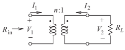
Figure \(\PageIndex{2}\): A transformer as a matching network. Port \(1\) is on the left or primary side and Port \(2\) is on the right or secondary side.
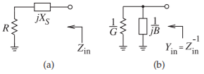
Figure \(\PageIndex{2}\): Matching using a series reactance: (a) the series reactive element; and (b) its equivalent shunt circuit.