
1.1: Procedure
- Page ID
- 26331

After logging into the computer, open Multisim. If a desktop shortcut is not available Multisim may be accessed via the Programs menu under the NI (National Instruments) menu item. This is a large program and may take a minute or two to load. Eventually, you will be greeted with something similar to the screen shown in Figure \(\PageIndex{1}\). As the toolbars are customizable, the precise look of the program may be a little different from that shown. In general, there are a series of toolbars along the top. These are used to select different components and editing or viewing functions. Multisim’s schematic capture facility is object based, that is, you “draw” a circuit by selecting predefined objects such as resistors and transistors, and drag them onto the workspace. They are then wired together using the mouse. You can zoom into or out of the workspace using the mouse.
By default, along the left edge is the Design Toolbox browser window. This may be closed to create more working room for the schematic. At the bottom is the tabbed Spreadsheet View that shows simulation data, components, etc. Clicking on entries will highlight the corresponding elements on the schematic worksheet. Along the right edge is a vertical toolbar that contains virtual instruments.
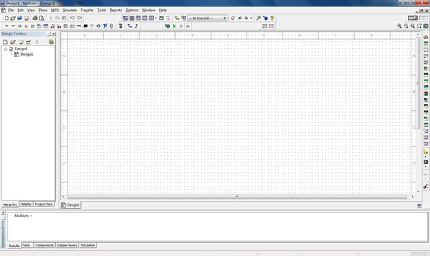
Figure \(\PageIndex{1}\)
Multisim uses three different kinds of components to create schematics. They are virtual basic and rated components, real (or manufacturer’s) components, and 3D virtual components. Virtual and real components use the standard industry schematic symbols. By default, components with physical footprints (most real components) are colored blue and components without a physical footprint (virtual components) are colored black. In contrast, 3D components look more like photographs of the actual component. Examples are shown in Figure \(\PageIndex{2}\). Although 3D components add a certain amount of color and realism to a circuit, Multisim contains few of them and thus are not used for simulations generally. We shall not discuss them further.
The difference bewteen virtual and real components is that real components reflect items from a manufacturer’s database. The items include physical parameters, such as size and pinouts, which are required for designing proper printed circuit boards. Also, real behavioral models for semiconductor devices such as op amps will be more accurate than the virtual models. Finally, the values of real passive components (resistors, capacitors and inductors) are limited to the nominal values specified by the manufacturer. In contrast, the values of virtual components can be set to almost anything, however, there are no corresponding physical data. As a consequence, if a PCB is needed, virtual components are not the appropriate choice. In practice, if the goal is to create a production circuit, real components will be used. If the goal is to simulate a lab exercise, virtual components will be used for the passives (rated resistors, capacitors and inductors) and reals will be used for the active components (transistors, diodes, op amps, etc.).
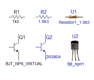
Figure \(\PageIndex{2}\)
To illustrate the use and editing of components, drag a DC voltage source onto the workspace. It will show up with a default voltage value and label. Double click the symbol. A dialog box will pop up next to it as shown in Figure \(\PageIndex{3}\).
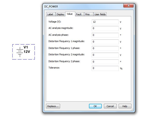
Figure \(\PageIndex{3}\)
From this dialog you can change a variety of attributes, the most important of which are the voltage value and the name. Double clicking any component will bring up a settings dialog box although the precise items contained within it will vary from component to component. For example, for a resistor there will be a resistance setting instead of a voltage setting. If you need to remove a component, simply select it and hit the Delete key.
Editing the position and orientation of a component is straight forward. Once the item is selected (shown by a surrounding dashed line) it may be moved using either the mouse or the cursor keys. If you need to move a group of components, the mouse may be used to select several items by clicking and then dragging the mouse over them. Every component within the selection box will be highlighted and will move as a group. Also note that it is possible to select the text labels of components and just move them. This can be handy if a label becomes obscured by a wire.
Components may also be rotated and flipped. These commands can be accessed from the main menu, however, it is handy to remember certain keyboard shortcuts (such as Ctrl-R, rotate right). You can also customize the tool bars and add these commands as their own buttons for easy access. The Customize dialog is shown in Figure \(\PageIndex{4}\) and is accessed via the Options menu.
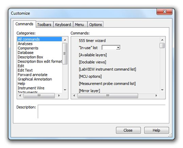
Figure \(\PageIndex{4}\)
Along with editing the components and customizing the tool bars, you may also customize the look of the work space. Go to the Options menu and select Sheet Properties. From here you can select a variety of color schemes for the components and wiring. You can also select which component items (labels, values, etc.) will be displayed. Fonts may be altered as well. Be forewarned, it is possible to spend a great deal of time trying to make the work space look pretty instead of doing truly productive work. Don’t fall into this trap. Before we close this dialog, there is one important setting to note and that is the section labeled “Net Names”. For now leave it as it is. We shall revisit this in the future.
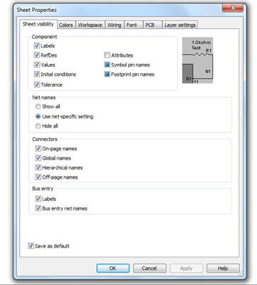
Figure \(\PageIndex{5}\)
OK, let’s create a circuit and perform a simulation. You should already have a DC voltage source on your work space. From the virtual (blue) components tool bars, select two resistors and an earth ground symbol. We shall make a series loop of the three elements with the negative end of the power supply at ground. One resistor will need to be rotated 90 degrees (one horizontal and one vertical). In order to wire the items together, simply click on the free lead of one component and move to the desired lead of another. While moving, Multisim will draw a ghost line. Clicking on the second component will create a proper wire (by default, colored red). Wires are always drawn along the horizontal and vertical with 90 degree bends, not directly from point to point. This is the proper way to draw a schematic in the vast majority of cases.
It is possible to click on the middle of a wire in order to tie multiple items together. A small node circle will be drawn at the connection point. To delete a wire, click on it to select it. You will see a set of small box “handles” around it. To remove the wire, simply hit the Delete key. Note that you can also move the wire with those handles if desired. In fact, it is possible to align wires at odd angles with these handles (again, this is not typical).
Note that if you move a component, Multisim will automatically move the wires along with it. You do not have to rewire it. Sometimes, especially if components are too close, the wire may be draw in an odd, looping form. The easiest solution is to simply separate the components a little more.
Once the components are in place and wired, double-click each component to set their values as shown in Figure \(\PageIndex{6}\). If you’re using power rated virtual resistors, also increase their power rating to one watt, each. We shall then add two the two voltmeters. Please note that it is perfectly acceptable to change the component values immediately after dragging them onto the work space; you don’t have to wait until they are wired together. It is suggested, though, that you decide upon a particular workflow and stick to it otherwise the chances of forgetting to change components from their default values increases.
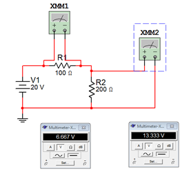
Figure \(\PageIndex{6}\)
To add the voltmeters (XMM1 and XXM2 in Figure \(\PageIndex{6}\)), select a virtual DMM from the top of the Instruments toolbar along the right edge of the screen. Drag this onto the work space and wire it across R1 as shown in Figure \(\PageIndex{6}\). Grab a second virtual DMM and repeat the process for R2. Now double click on the DMMs. Two small windows will pop up (they might overlap each other, if so, move one over). Select the V (voltage) button and the straight line (DC) button on each of them. The circuit is now ready to perform a simulation.
To start a simulation, you can select the the rocker switch located in the upper right corner of the menu area. This is the virtual on-off switch. Alternately, you can select Run from the Simulate menu or use the green Run button on the simulation toolbar. In a moment, you should see voltages appear on the two virtual DMMs. In order to edit the circuit, the simulation must be turned off. So, if we wish to add or delete components, we must remember to “power down” the circuit just as we would in a real lab. To be safe, do this now.
Multisim has a wide variety of virtual instruments. Some of them are fairly simple such as the DMM just used. Other instruments are virtual recreations of real-world test instruments. For example, from the Instruments toolbar select the Tektronix Oscilloscope. You may place this anywhere on your schematic. Now double click on the small icon for this device (XSC1). A rather ornate window opens which appears to be the front panel of a Tektronix TDS 2024 oscilloscope, similar to the models you might see in electronics labs, right down to subtle shadows around the knobs! See Figure \(\PageIndex{7}\). This has the advantage of immediacy (assuming you’ve used this type of oscilloscope before), however, it is not the ultimate way to perform a simulation. We will look at even more powerful and flexible ways of creating simulations in the next exercise. For now, you may wish to delete this new instrument from the work space and then save the existing schematic. Remember to always save to either your student account or to a USB drive. Never save directly to the hard drive in lab.
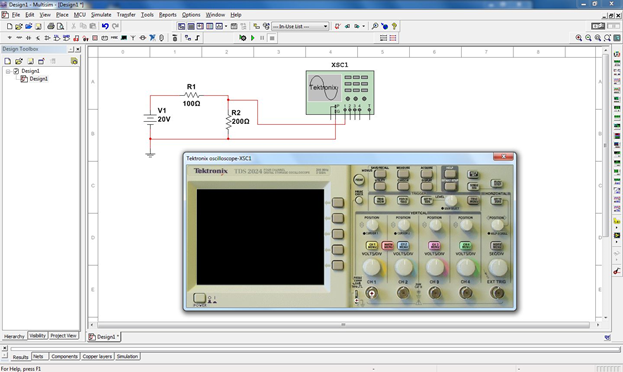
Figure \(\PageIndex{7}\)
There are three very good “every day” uses for Multisim during your studies: First, it is a very handy tool for verifying lab results. That is, you can recreate a lab circuit, simulate it, and compare the simulation to both your theoretical calculations and lab measurements. Second, it is a handy tool for checking homework if you get stuck on a problem. Third, it is convenient for the creation of schematics, for example, for a lab report. An easy way to do this is to draw the circuit, capture the screen image (Windows key+Print Screen key copies it into the clipboard) and then paste the image into your favorite image manipulation program. From there you can crop it, change contrast, etc. as needed and then paste the modified image into your lab report.
At this point you may wish to experiment a bit by rewiring the circuit to measure current or to try building new circuits. As with any tool, continued practice will hone your skill. Once you are done and have saved the file (the extension should be .msX where X is the Multsim version number), close Multisim and then shut down the computer.