
15.4: IGBT Applications
- Page ID
- 25350

IGBTs lend themselves to a variety of high power switching applications. In this section, we shall look at four of them. Bear in mind that power BJTs and power EMOSFETs might also be used for these applications, depending on the specifics of the design. In general, power E-MOSFETs will be preferred when using high switching frequencies at medium to low powers and voltages, while IGBTs are favored at higher voltages, currents and powers.
15.4.1: Induction Heating
Although thermal conduction is the first method commonly thought of when it comes to heating something, magnetic induction may also be used. Magnetic induction creates heat through the Joule effect and can be used for large scale industrial processes, such as creating metal alloys via an induction furnace, to much smaller scale consumer applications, such as an inductive cooktop. Induction heating is efficient because the vessel itself is heated directly and less heat is lost to the immediate environment. Also, control of heating can be very precise. The basic idea is to create a rapidly changing magnetic field placed next to the container to be heated. If this vessel is ferromagnetic, eddy currents will be induced in the vessel, creating heat. Thus, if we were to place a cast iron pot within the field, the pot itself would heat up as eddy currents are induced within it, thus heating the pot's contents. There are no open flames or surface heating elements involved. The only downside to this process is that the vessel must be made of ferromagnetic material. For a cooktop, that means that pots and pans must be made of iron or certain steel alloys. An aluminum sauté pan or ceramic container will not work with this system.
As an example, let's consider an inductive cooktop. A sophisticated design could feature a full- or half-bridge arrangement of IGBTs, but for illustrative purposes we'll focus on a simple single-ended system using just one IGBT.
The system features four main components: the rectifier/EMI filter, the control/drive circuit, the IGBT switch and the \(LC\) resonant tank sub-circuit that generates the field. This is illustrated in Figure \(\PageIndex{1}\).
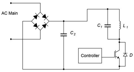
Figure \(\PageIndex{1}\): Simple inductive heater.
The rectifier produces full-wave pulsating DC, and the associated capacitor, \(C_2\), is used to help minimize EMI (electromagnetic interference) and also provide a return path for the tank. The control circuit produces a variable duty cycle pulse train to drive the gate of the IGBT. The greater the duty cycle, the longer the on-state of the IGBT, and ultimately, the greater the heating. Between the IGBT and the rectified power signal is a parallel resonant tank circuit comprised of \(C_1\) and \(L_1\). The inductor is comprised of a series of loops of large gauge wiring or copper tubing embedded in the cook surface, typically under a glass or ceramic top. The resonant frequency of the tank is tuned to the frequency of the controlling pulse train. This will maximize the tank current and thus produce a more powerful magnetic field. The switching frequency is usually placed just above the range of human hearing to avoid audible microphonics.1 Values in the range of 20 kHz to 30 kHz are typical, and the base frequency may change as the heat demand changes. For example, to minimize switching losses, the controlling frequency might start at 30 kHz for modest heating and decrease to 20 kHz for maximum heating.
From the cook's perspective there is no change between using the inductive cooktop and an ordinary electric cooktop using resistive heating elements: The cook places the pot or pan on the surface, under which lies the coil. A heat level control knob is provided for them to adjust the heat intensity. To their advantage, when they remove the pot or pan, the cooking surface itself will not be as hot as an ordinary cooktop.
From the designer's perspective, the heat control knob simply changes the duty cycle of the controlling pulse train (and optionally, its frequency, as mentioned previously). Other refinements might include sensing whether or not a vessel is on the cooktop and throttling back control if nothing is detected. Finally, an even simpler system could switch the IGBT on and off at a much slower rate (think in terms of seconds) to greatly reduce switching losses but this runs the risk of heat cycling if the pots and pans used are of very light gauge construction (i.e., their thermal time constant will be faster).
15.4.2: DC-to-AC Inversion
There are many instances where we wish to derive an AC voltage from an existing DC voltage. Examples include an uninterruptible power supply (UPS) that would draw current from a battery and deliver standard AC power when there is a disruption in the power grid, and the need to operate electronic devices designed for the home in a remote location. This process is known as DC-to-AC inversion.
The simplest method to create AC from DC is to just “chop” the DC at the desired line frequency and then scale it, that is, feed the DC into a simple IGBT switch which will produce a square wave and then feed the square wave into a transformer to arrive at the desired voltage. The obvious problem with this technique is that the AC signal will not be a nice, smooth sine wave, but rather, a distorted square wave. Unfortunately, for many electronic components this will present a challenge to their power supply circuits. A possible refinement involves making a step-wise approximation of a sine wave but this is still not ideal.
A more accurate scheme involves synthesizing a sine wave via PWM. We still chop the DC, but now the action is performed at a higher frequency and with a varying duty cycle such that, when the output is averaged, we arrive at a sine wave. A block diagram of this scheme is shown in Figure \(\PageIndex{2}\).
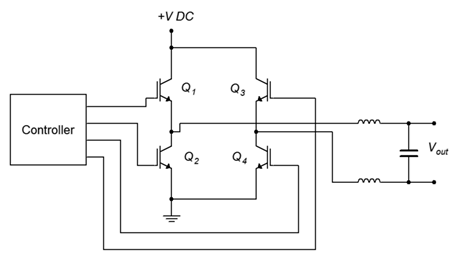
Figure \(\PageIndex{2}\): DC-to-AC inverter (antiparallel diodes not shown).
The controller generates a set of PWM signals to drive the four IGBTs configured as a full-bridge. The bridge output is then fed to a balanced LC filter that removes the high frequency PWM components, leaving a smoothed sine wave. This signal can be used as is, or fed into a step-up transformer if the desired AC voltage is greater than the starting DC voltage. An example of this would be the need to supply a device designed to run on 120 VAC from the nominal 12 VDC system found in a car.
There is a side item worthy of mention here. Some devices derive timing signals from the line frequency (a classic example is an electronic alarm clock/radio). This is possible because the power generation utility monitors this frequency with great accuracy. If the controller shown in Figure \(\PageIndex{2}\) does not produce an accurate base frequency, then that clock/radio will not tell time accurately.
15.4.3: Motor Control
IGBTs can be used to control the speed of electric motors. The configuration of the control circuit will depend on the kind of motor being controlled. In simplest terms, the speed of a DC motor is controlled by the voltage applied to it: the higher the voltage, the higher the speed. In contrast, the speed of an AC motor depends on the frequency of the applied source (they are proportional).
Controlling a DC motor is a straightforward situation. If all we need to do is start and stop the motor, the IGBT can be inserted in series with the motor and used as a switch to open and close the circuit. Being solid-state, the IGBT has numerous advantages over a mechanical switch or relay including long-term reliability and simplicity of the control circuit. To alter the speed, the IGBT can be controlled via PWM. This is illustrated in Figure \(\PageIndex{3}\).
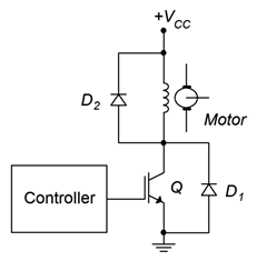
Figure \(\PageIndex{3}\): DC motor control via IGBT.
\(D_1\) and \(D_2\) are flyback or snubber diodes used for protection from inductive current spikes caused by the motor's current being switched on and off. As noted earlier, some IGBTs are co-packaged with an anti-parallel diode (\(D_1\)).
To vary the motor's speed, the controller produces a PWM drive signal. The smaller the duty cycle of this pulse train, the lower the average applied voltage to the motor, and therefore the slower its speed. The base frequency of the PWM signal does not have to be particularly high in this scenario; a few hundred hertz may prove sufficient. This will help minimize switching losses.
For an AC motor the situation is a little more complex. One approach is to use the PWM technique explained under the DC-to-AC converter section. The difference is that the power source would not be DC, but rather, AC. Consequently, we would need to transform the AC power source into a more usable signal and then apply the circuit depicted in Figure \(\PageIndex{2}\) to power the motor. The controller itself will need to be considerably more sophisticated. In Figure \(\PageIndex{2}\), the duty cycle is continuously changed such that the “area under the curve” approximates a sine wave. Eventually, the pattern will repeat itself for subsequent cycles of the sine wave. In other words, the rate at which the pattern repeats is the sine wave's period. In the DC-to-AC inverter application, this rate never changes because we need a constant output frequency (e.g., 60 Hz). In the AC motor control application, such is not the case. This repetition rate needs to be adjustable because that's what controls the motor's speed. One way to do this is to simply increase the base frequency of the PWM pulse train. This method is simple and direct but has the disadvantage of creating more transient edges per unit time and therefore tends to increase switching losses. An alternate approach is to keep the base frequency constant and instead alter the duty cycle pattern. This helps minimize the switching loss issues but has the disadvantage of requiring a more complex control circuit and possibly producing a lower quality sine wave at higher output frequencies.
15.4.4: DC-to-DC Conversion
Our final application is DC-to-DC up-conversion, that is, producing a new DC voltage that is higher than the original source and also capable of high output current (voltage doublers and triplers can be made from diode/capacitor lattices but they are not designed to deliver high, continuous currents). Applications requiring up-conversion include photovoltaic systems (i.e, combining the outputs of several solar panels and tying them into the power system) and high output car audio systems. Specifically, the nominal 12 volt automotive power system is insufficient to supply an amplifier intended to deliver hundreds or even thousands of watts to a subwoofer. The 12 volt source will need to be increased, perhaps by a factor of ten, to achieve the desired output levels.2
As we have already seen how DC can be translated into AC via an inverter, it is possible to simply rectify and filter the new AC, producing a higher DC level. This scheme is illustrated in Figure \(\PageIndex{4}\).
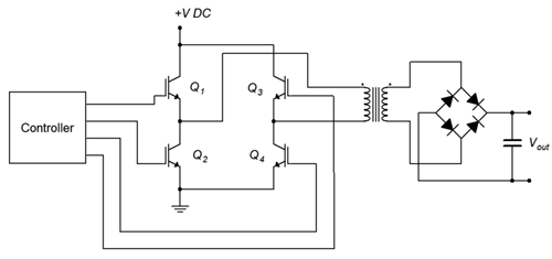
Figure \(\PageIndex{4}\): DC-to-DC conversion via transformer (anti-parallel diodes not shown).
The transformer pictured here will need to be a step-up variety in order to achieve the desired output voltage level. Note that the AC generation side does not have to produce a particularly nice sine wave nor does it have to be at the usual line frequency. In fact, increasing the frequency will likely result in reduced sizes for the transformer and filter capacitors.
A completely different approach is to use a switching regulator. Switching regulators use a feedback control system to generate a very stable output voltage by comparing it to a reference voltage. They can be configured in step-down, step-up or polarity inversion forms.3 In this case, we can use the step-up, or boost, form. An example is shown in Figure \(\PageIndex{5}\).
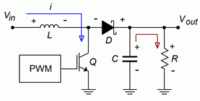
Figure \(\PageIndex{5a}\): Step-up switching regulator, on-state.
As with the other applications presented so far, the IGBT is being used as a switch. Figure \(\PageIndex{5a}\) illustrates the on-state of the IGBT. During this phase, current is drawn through the inductor, \(L\), storing energy in the associated magnetic field. The reverse-biased Schottky diode, \(D\), isolates this section from the output section, where \(C\) is delivering the load voltage and current.
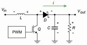
Figure \(\PageIndex{5b}\): Step-up switching regulator, off-state.
The off-state is depicted in Figure \(\PageIndex{5b}\). During this portion, the inductor discharges and appears as a source. As it is in series with the input voltage, the voltage at the output will equal the inductor's voltage plus the input voltage. Also, during this phase the capacitor is recharged, ready for the next on-state of the IGBT. Note that a Schottky diode is used here because it exhibits fast switching times and a low forward voltage drop. Switching frequencies for these circuits tend to be high (100 kHz and up are common) as that minimizes the sizes of the inductor and capacitor.
References
1Granted, it may still fall within the hearing range of your dog, so don't be surprised if your border collie prefers a gas cooktop to make a balsamic reduction.
2In the process, the current demand will be increased greatly as well, perhaps beyond the capabilities of the vehicle's alternator (which will also require upgrading), but these are the prices one must pay if one desires very high sound pressure levels in what is arguably the worst acoustical environment in which to listen to music. Of course, we should also admit that the act of critically listening to and enjoying music may not be the point of such an exercise.
3For details on switching regulators, see Fiore, J, Operational Amplifiers and Linear Integrated Circuits: Theory and Application, another free OER text.