
3.4: Combining Series Components
- Page ID
- 25108

Typically, a series connection will include multiple resistors. Referring back to the resistance equation presented in Chapter 2, Equation 2.7.2, we can see that resistors in series add.
Figure 3.4.1 : Resistors in series.
\[R = \frac{\rho l}{A} \nonumber \]
If we consider two identical resistors placed in series, one after the other as in Figure 3.4.1 , the effective length would double while keeping the resistivity and area unchanged. The combined result would be a doubling of the resistance of just one of them. If we then generalize this to two arbitrary resistors of identical resistivity and area, the lengths would dictate the resistance of each, and the combined lengths would then reflect the resistance of the pair. We can generalize this further for \(N\) resistors. Thus we find that the equivalent resistance of a group of series resistors is their sum:
\[R_{Total} = R_1+R_2+R_3+\dots +R_N \label{3.2} \]
Consequently, as resistors in series add, total resistance may be found by summing the individual resistors.
A string of resistors is placed in series as shown in Figure 3.4.2 . Their values are: 120 \(\Omega \), 390 \(\Omega \), 560 \(\Omega \) and 470 \(\Omega \). Determine the equivalent series value.
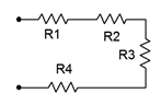
Figure 3.4.2 : Resistor string for Example 3.4.1 .
\[R_T = R_1+R_2+R_3+R_4 \nonumber \]
\[R_T = 120 \Omega +390 \Omega +560\Omega +470\Omega \nonumber \]
\[R_T =1540\Omega \nonumber \]
Multiple voltage sources in series may also be added, however, polarities must be considered as opposing voltages partially cancel each other (i.e., adding a negative). This concept is presented in the next example.
Determine the equivalent series value of the voltage sources presented in Figure 3.4.3 .
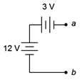
Figure 3.4.3 : Voltage sources in series.
If we use point \(b\) as our reference, by inspection the top of the 12 volt source is 12 volts above point \(b\) (reminder, the long bar denotes the positive terminal). Also, by inspection, the right side of the 3 volt source (point \(a\)) is negative with respect to its left side. As the left side of this source is connected to the positive terminal of the 12 volt source, then it too must be 12 volts above point \(b\). As its right side is 3 volts less than this side, point \(a\) must be 3 volts less than 12 volts, or 9 volts above point \(b\). Thus \(V_{ab}\) = 9 volts.
Chasing this further, if the 3 volt source had been flipped so that it had the same polarity as the 12 volt source (positive toward the right) then \(V_{ab}\) = 15 volts. If the 12 volt source had been flipped (positive toward bottom) with the 3 volt source as drawn originally, then \(V_{ab}\) = −15 volts. If both sources had been flipped then \(V_{ab}\) = −9 volts. Finally, if point \(a\) had been taken as the reference then these four potentials would have the opposite polarity because, by definition, \(V_{ba} = −V_{ab}\).
In contrast to voltage sources, differing current sources are not placed in series as they would each attempt to establish a different series current, a practical impossibility. Refer to Figure 3.4.4 as a reminder!
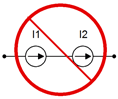
Figure 3.4.4 : Placing current sources in series generally is evil.