
5.4: Quantum Capacitance in FETs
- Page ID
- 51615

Unfortunately, Equations. (5.3.4) and (5.3.5) typically must be solved iteratively. But insight can be gained by studying a FET with a few approximations.
Another way to think about charging is to consider the effect on the channel potential of incremental changes in \(V_{GS}\) or \(V_{DS}\). We can then apply simple capacitor models of channel charging to determine the channel potential in Equation (5.3.6).
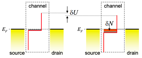
If the potential in the channel changes by \(\delta U\) then the number of charges in the channel changes by
\[ \delta N = -g(E_{F})\delta U \nonumber \]
Note that we have assumed T = 0K, and note also the negative sign – making the channel potential more negative increases the number of charges.
Substituting back into Equation (5.3.4) gives
\[ \delta U = -q \delta V_{GS} \frac{C_{G}}{C_{ES}}-q \delta V_{DS} \frac{C_{D}}{C_{ES}}-\frac{q^{2}}{C_{ES}}g(E_{F})\delta U \nonumber \]
Collecting \(\delta U\) terms gives
\[ \delta U = -q \delta V_{GS} \frac{C_{G}}{C_{ES} +C_{Q}}-q \delta V_{DS} \frac{C_{D}}{C_{ES}+C_{Q}} \nonumber \]
Where we recall the quantum capacitance (\(C_{Q}\)):
\[ C_{Q}=q^{2}g(E_{F}) \nonumber \]
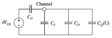
Using the quantum capacitance, we can easily construct a small signal model for changes in \(V_{GS}\) or \(V_{DS}\). See, for example the small signal \(V_{GS}\) model in Figure 5.4.2. Note that the value of the quantum capacitance depends on the channel potential at the bias point.
Using Equation (5.4.1) we can also determine a small signal model for the charge in the channel.
\[ q\delta N=\delta V_{GS} \frac{C_{G}C_{Q}}{C_{ES}+C_{Q}} \nonumber \]
In the next section we will consider FET operation under two limiting cases: (i) when \(C_{Q}\) is large relative to \(C_{ES}\), and (ii) when \(C_{Q}\) is small. The two cases typically correspond to the ON and OFF states of a FET, respectively.