
6.5: High Speed Amplifiers
- Page ID
- 3583

There are many applications where amplification in the 1 MHz to 100 MHz region is desired. In this range falls the broadcast spectrums of FM radio, VHF television, citizen's band radio, and video processing in general. The bulk of general-purpose op amps exhibit \(f_{unity'}\)s in the 1 MHz to 10 MHz range. Also, slew rates tend to be below 20 V/\(\mu\)s. These characteristics make them wholly unsuitable for higher frequency applications. Even standard “fast” op amps like the LM318 offer\(f_{unity'}\)s of no more than 20 MHz with 50 V/\(\mu\)s slew rates.
In contrast to general-purpose devices, “ultra fast” op amps exhibit gain bandwidth products in excess of 50 MHz and slew rates over 100 V/\(\mu\)s. Devices are available with slew rates greater than 1000 V/\(\mu\)s and others boast gain bandwidth products around 1 GHz. In order to optimize performance, these devices are normally of the uncompensated variety. In this way, the largest possible bandwidth is produced for any given gain.
Of course, when working with such fast devices, circuit layout is far more critical than normal. A very good circuit design may be crippled by a careless layout. First of all, PC-board ground planes are advised. A ground plane offers isolation along with low resistance and inductance pathways. These parasitic and stray impedance effects, which are often ignored at lower frequencies, can reduce circuit performance at high frequencies. Shielding around input and output paths may also be required for some applications, but care must be exercised, as the resulting capacitance may also produce high-frequency attenuation. In general, the circuit layout should minimize stray capacitance between the output and feedback point, from the feedback-summing node to ground, and between the circuit input and output. One common technique involves extending a ground plane in order to isolate the input and output traces. Also, the traces should be kept short to minimize coupling effects, and thus, compact layouts are generally preferred. IC sockets are generally avoided due to the increased lead inductance and capacitance they present. When breadboarding high speed circuits, the popular multi-row socket boards used for general purpose work are normally unacceptable due to high lead inductance and capacitance effects. Finally, as with power op amps, some high-speed op amps have been optimized for specific applications and are no longer interchangeable with the generic op amp model. For example, specific gains may be selected by grounding or opening certain pins on the IC.
The MAX4030/4031 family from Maxim are low-cost dual and triple high speed op amps. They boast typical specs of 115 V/\(\mu\)s for slew rate and 144 MHz for gain bandwidth product. The devices run from a 5 volt supply. As with any high frequency device, power supply bypass capacitors are required. As an example a basic 75 \(\Omega\) video line driver is shown in Figure \(\PageIndex{1}\). Another example is the AD847 from Analog Devices which boasts a 300 V/\(\mu\)s for slew rate with a 50 MHz gain-bandwidth product.
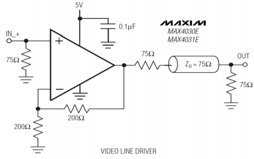
Figure \(\PageIndex{1}\): Video driver. Reprinted courtesy of Maxim Integrated