
8.2: The Need for Regulation
- Page ID
- 3594

Modern electronic circuits require stable power supply voltages. Without stable potentials, circuit performance may degrade, or if variations are large enough, the circuit may cease to function all together and various components may be destroyed. There are many reasons why a power supply may fluctuate. No matter what the cause, it is the job of the regulator to absorb the fluctuations, and thereby maintain constant operating potentials.
A basic power supply circuit is shown in Figure \(\PageIndex{1}\). First, a transformer is used to isolate the circuit from the AC power source. It is also used to step down (or step up) the AC source potential to a more manageable level. A rectifier then converts the scaled AC signal to pulsating DC, in the form of either half-wave or, more typically, full-wave rectification. The variations in the pulsating DC signal are then filtered out in order to produce a (hopefully) stable DC potential, which feeds the load. The filter may take the form of a simple capacitor or, possibly, more complex networks comprising both capacitors and inductors.
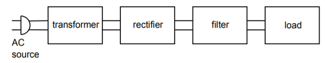
Figure \(\PageIndex{1}\): Basic power supply.
There are two main causes of power supply output variation. First, if the AC source signal changes, a proportional change will be seen at the output. If, for example, a brown out1 occurs, the nominal 120 V AC source used in the US, may drop to, say, 100 V AC. This represents a decrease of one sixth, or about 16.7%. This same change will be reflected by the transformer, so the output of the transformer will be about 16.7% low as well. This reduction carries right through the rectifier and filter to the load. In some circuits, this will not present a major problem. For example, this may mean that an op amp will be running off a 12 V supply instead of a 15 V supply. On the other hand, a TTL logic circuit may not operate correctly if only 4 V instead of 5 V are applied. Of course, if an over-voltage occurred, both the op amp and the logic circuit could be damaged.
How well a circuit handles variations in the AC line signal is denoted by the parameter, line regulation.
\[ Line \ Regulation = \frac{V_{max} − V_{min}}{V_{min}} \times 100 \label{8.1} \]
where \(V_{max}\) is the load voltage produced at the maximum AC line potential and \(V_{min}\) is the load voltage for the lowest AC line potential. Normally, this value is expressed as a percentage. Ideally, a power supply will always produce the same output potential, and therefore, the perfect line regulation figure would be 0%.
The other major source of supply variation is variation of load current. Indeed, load current variations can be far greater than the usual variations seen in the AC line. This normally has the effect of increasing or decreasing the amount of AC ripple seen in the output voltage. Ideally, there would be no ripple in the output. Ripple is caused by the fact that heavy load currents effectively reduce the discharge time constant of the filter. The result is that the filter gives up its stored energy faster and cannot successfully “fill in the gaps” of the pulsating DC signal fed to it. The ripple signal is effectively an AC signal that rides on the DC output. This rapid variation of supply potential can find its way into an audio or signal processing path and create a great deal of interference. Along with this variation, the effective DC value of the supply may drop as the load current is increased. The figure of merit for stability in spite of load changes is called load regulation.
\[ Load \ Regulation = \frac{V_{max} −V_{min}}{V_{min}} \times 100 \label{8.2} \]
where \(V_{max}\) is the largest load voltage produced, and \(V_{min}\) is the minimum load voltage produced. These points usually occur at the minimum and maximum load currents, respectively. Again, this value is normally expressed as a percentage and would ideally be 0%.
In order to maintain a constant output voltage, the power supply regulator needs to sense its output and then compensate for any irregularities. This implies a number of things. First, some form of reference is needed for stable comparison to the output signal. Second, some form of comparator or amplifier is required in order to make use of this comparison. Finally, some form of control element is needed to absorb the difference between the input to the regulator circuit and the desired output. This control element may either appear in series or in parallel with the load, as seen in Figure \(\PageIndex{2}\). The first form is shown in Figure \(\PageIndex{2a}\) and is normally referred to as a series mode regulator. The control element allows current to pass through to the load, but drops a specific amount voltage. The voltage that appears across the control element is the difference between the filter's output and the desired load voltage.
Figure \(\PageIndex{2b}\) shows a shunt mode regulator. Here, the control element is in parallel with the load and draws enough current to keep the output level constant. For many applications, shunt mode regulators are not as efficient as series mode regulators are. One example of a simple shunt mode regulator is the resistor/Zener diode arrangement shown in Figure \(\PageIndex{3}\). Note that under no-load conditions (i.e., when the load impedance is infinite) considerable current flows in the regulating circuit.
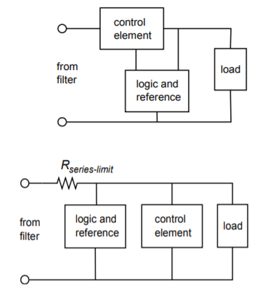
Figure \(\PageIndex{2}\): Two forms of regulator control elements. a. Series regulator (top). b. Parallel regulator (bottom).
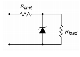
Figure \(\PageIndex{3}\): Simple zener shunt regulator.
References
1A reduction in the standard supplied potential may be introduced by a power utility as a way of dealing with particularly heavy load conditions, such as on a very hot summer day when numerous air conditioners are running.