
11.10: Switched-Capacitor Filters
- Page ID
- 28515

Our final topic is the class of ICs known as switched-capacitor filters. These are just specific realizations of the types of filters that we have already examined. Generally, switched-capacitor filters come in two types: fixed order and alignment, and universal (state-variable based). A typical fixed IC might offer a sixth-order lowpass Butterworth filter. The number of external components required is minimal. The universal types offer most of the flexibility of the state-variable designs discussed previously. Both types are tunable and are relatively easy to use. Tuning is accomplished by adjusting the frequency of an external clock signal. The higher the clock frequency, the higher the resulting critical frequency. These ICs offer a convenient “black box” approach to general-purpose filter design. As is the case with most special-purpose devices, individual manufacturer's data sheets will give the specific application and design procedures for their parts.
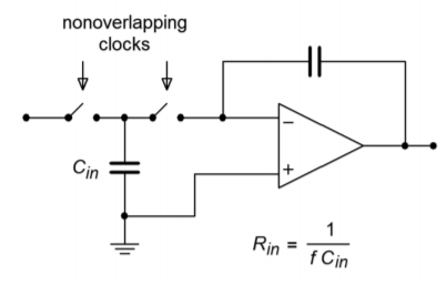
Figure \(\PageIndex{1}\): Switched capacitor circuit.
The concept behind the switched-capacitor filter is quite interesting. The basic idea is to mimic a resistor through the use of a capacitor and a pair of alternating switches. As an example, a simple integrator is shown in Figure \(\PageIndex{1}\). As you have already seen, integrators are little more than first-order, low-pass filters. In this circuit, the input resistor has been replaced with a capacitor, \(C_{in}\), and a pair of switches. These switches are controlled by a non-overlapping bi-phase clock. This means that when one switch is closed, the other will be open, and that during switching, one switch will break contact before the other switch makes contact. (This is sometimes referred to as a “break before make” switch.)
During the first half of the clock cycle, \(C_{in}\) charges to the value of \(V_{in}\). During the second half of the cycle, this charge is transferred to the integration capacitor. Therefore, the total charge transferred during one clock cycle is
\[Q=C_{in} V_{in} \label{11.25} \]
The flow of charge versus time defines current, so the average input current is
\[I_{in} = \frac{Q}{T_{clock}} \label{11.26} \]
Substituting Equation \ref{11.25} into Equation \ref{11.26} yields
\[I_{in} = C_{in} \frac{V_{in}}{T_{clock}} \label{11.27} \]
Because the input resistance is defined as the ratio of \(V_{in}\) to \(I_{in}\), and recognizing that \(f_{clock}\) is the reciprocal of \(T_{clock}\), Equation \ref{11.27} is used to find \(R_{in}\):
\[R_{in} = \frac{1}{C_{in} f_{clock}} \label{11.28} \]
Equation \ref{11.28} says two important things: first, because \(R_{in}\) sets the input impedance, it follows that input impedance is inversely proportional to the clock frequency. Second, because \(R_{in}\) is used to determine the corner frequency (in conjunction with the integration/feedback capacitor), it follows that the critical frequency of this circuit is directly proportional to the clock frequency. In other words, a doubling of clock frequency will halve the input impedance and double the critical frequency. Depending on the actual design of the IC, there will be a constant ratio between the clock frequency and the critical frequency. This is a very useful attribute. It means that you can make a tunable/sweepable filter by using one of these ICs and an adjustable square wave generator. For that matter, anything that can produce a square wave (such as a personal computer) can be used to control the filter response.
Typically, the ratio of clock frequency to critical frequency will be in the range of 50 to 100. The lower limit of clock frequency is controlled by internal leakage paths that create offset errors. The upper limit is controlled by switch settling time, propagation delays, and the like. A range of 100 Hz to 1 MHz is reasonable. This means that the entire audio frequency range is covered by these devices. For use at the highest frequencies, or with high impedance sources, an input buffer amplifier should be used.
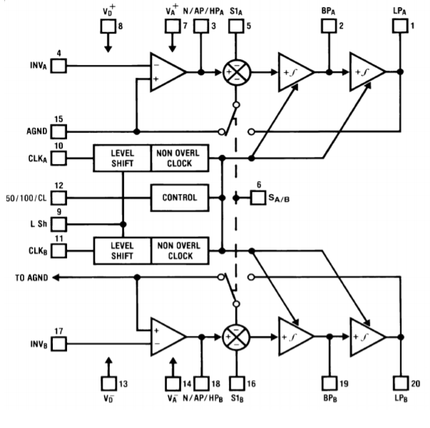
Figure \(\PageIndex{2}\): Block diagram of the MF10. Reprinted courtesy of Texas Instrutments
An example of a switched capacitor filter IC is the MF10, shown in Figure \(\PageIndex{2}\). The MF10 is a dual second-order filter that can be connected in a variety of modes. Mode three is the general purpose state variable form and is shown in Figure \(\PageIndex{3}\). Combining the two sections can produce fourth-order systems. In all cases, the external component count is minimal.
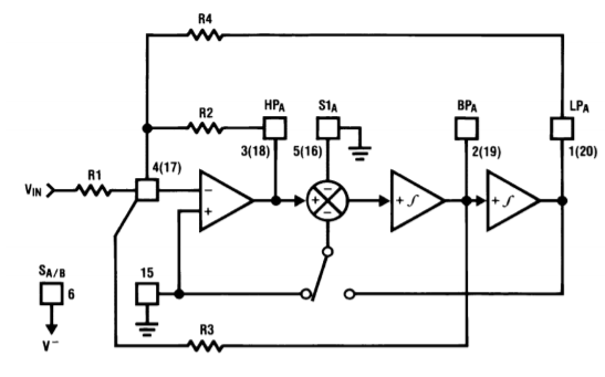
Figure \(\PageIndex{3}\): MF10 mode 3 (state variable) equivalent. Reprinted courtesy of Texas Instrutments
An example of a fourth-order filter is shown in Figure \(\PageIndex{4}\). As you can see, the design is sparse, using only four resistors per section. In short, devices like the MF10 are good choices for general-purpose filter work, particularly when space and tuning considerations are important.
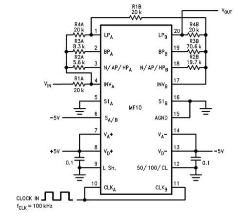
Figure \(\PageIndex{4}\): MF10 fourth-order low-pass Chebyshev filter. Reprinted courtesy of Texas Instrutments
Another device of interest is the LTC1068 from Linear Technology. The LTC1068 is a quad device, so a cascaded response of up to eighth-order is possible. Because these filters are basically little more than a switched capacitor version of the statevariable, a wide range of response types are possible. These include the high-pass, low-pass, band-pass and band-reject outputs, as well as a variety of alignments including Bessel, Butterworth, and Chebyshev. The LTC1068 is modular, so its internal op amps may be used as gain blocks or for creating a notch output without added external op amps (as seen in Example 11.8.1). Normally, no more than four or five external components (resistors and capacitors) are needed to realize a given filter function. Component calculation procedures are specified by the manufacturer.
Although switched-capacitor filters offer relatively quick and physically small realizations, they are not perfect. First of all, clock feedthrough is typically in the range of 10 mV, meaning that 10 mV of clock signal “leaks” into the output. Fortunately, this signal is much higher than the critical frequency, but may cause some problems for low-noise applications. Another problem arises from the fact that switched capacitor filters are actually sampled data devices. As you will see in the next chapter, sampled data devices may suffer from a distortion producing phenomenon called aliasing. In order to avoid aliasing, the input signal must not contain any components that are greater than one-half of the clock frequency. For example, if the MF10 is used to create a 1 kHz filter with a 50 kHz clock, no component of the input signal may exceed 25 kHz (one-half of the clock) if aliasing is to be avoided. If this requirement cannot be guaranteed, some form of pre-filtering is needed. Within these limits though, switched capacitor filters make light work out of many general-purpose applications.