
5.16: Exercises
- Page ID
- 41120
\( \newcommand{\vecs}[1]{\overset { \scriptstyle \rightharpoonup} {\mathbf{#1}} } \) \( \newcommand{\vecd}[1]{\overset{-\!-\!\rightharpoonup}{\vphantom{a}\smash {#1}}} \)\(\newcommand{\id}{\mathrm{id}}\) \( \newcommand{\Span}{\mathrm{span}}\) \( \newcommand{\kernel}{\mathrm{null}\,}\) \( \newcommand{\range}{\mathrm{range}\,}\) \( \newcommand{\RealPart}{\mathrm{Re}}\) \( \newcommand{\ImaginaryPart}{\mathrm{Im}}\) \( \newcommand{\Argument}{\mathrm{Arg}}\) \( \newcommand{\norm}[1]{\| #1 \|}\) \( \newcommand{\inner}[2]{\langle #1, #2 \rangle}\) \( \newcommand{\Span}{\mathrm{span}}\) \(\newcommand{\id}{\mathrm{id}}\) \( \newcommand{\Span}{\mathrm{span}}\) \( \newcommand{\kernel}{\mathrm{null}\,}\) \( \newcommand{\range}{\mathrm{range}\,}\) \( \newcommand{\RealPart}{\mathrm{Re}}\) \( \newcommand{\ImaginaryPart}{\mathrm{Im}}\) \( \newcommand{\Argument}{\mathrm{Arg}}\) \( \newcommand{\norm}[1]{\| #1 \|}\) \( \newcommand{\inner}[2]{\langle #1, #2 \rangle}\) \( \newcommand{\Span}{\mathrm{span}}\)\(\newcommand{\AA}{\unicode[.8,0]{x212B}}\)
- The Thevenin equivalent output impedance of each of the amplifiers in Figure 5.12.8(a) is \(5\:\Omega\), and the system impedance, \(R_{0}\), is \(75\:\Omega\). Choose the transformer windings for maximum power transfer. [Parallels Example 5.12.4]
- A spiral inductor is modeled as an ideal inductor of \(10\text{ nH}\) in series with a \(5\:\Omega\) resistor. What is the \(Q\) of the spiral inductor at \(1\text{ GHz}\)?
- Consider the design of a \(50\text{ dB}\) resistive \(\mathsf{T}\) attenuator in a \(75\:\Omega\) system. [Parallels Example 5.5.1]
- Draw the topology of the attenuator.
- Write down the design equations.
- Complete the design of the attenuator.
- Consider the design of a \(50\text{ dB}\) resistive Pi attenuator in a \(75\:\Omega\) system. [Parallels Example 5.5.1]
- Draw the topology of the attenuator.
- Write down the design equations.
- Complete the design of the attenuator.
- A \(20\text{ dB}\) attenuator in a \(17\:\Omega\) system is ideally matched at both the input and output. Thus there are no reflections and the power delivered to the load is reduced by \(20\text{ dB}\) from the applied power. If a \(5\text{ W}\) signal is applied to the attenuator, how much power is dissipated in the attenuator?
- A resistive Pi attenuator has shunt resistors of \(R_{1} = R_{2} = 294\:\Omega\) and a series resistor \(R_{3} = 17.4\:\Omega\). What is the attenuation (in decibels) and the characteristic impedance of the attenuator?
- A resistive Pi attenuator in a system with characteristic impedance \(Z_{0}\) has equal shunt resistors of \(R_{1} = R_{2}\) and a series resistor \(R_{3}\). Show that \(Z_{0} = \sqrt{(R_{1}^{2}R_{3})/(2R_{1} + R_{3})}\) and the attenuation factor \(K = \sqrt{(R_{1} + Z_{0})/(R_{1} − Z_{0})}\). [Start with Equation (5.5.2).]
- Design a resistive Pi attenuator with an attenuation of \(10\text{ dB}\) in a \(100\:\Omega\) system.
- Design a \(3\text{ dB}\) resistive Pi attenuator in a \(50\:\Omega\) system.
- A resistive Pi attenuator has shunt resistors \(R_{1} = R_{2} = 86.4\:\Omega\) and a series resistor \(R_{3} = 350\:\Omega\). What is the attenuation (in decibels) and the system impedance of the attenuator?
- Derive the \(50\:\Omega\) scattering parameters of the ideal transformer shown below where the number of windings on the secondary side (Port \(\mathsf{2}\)) is twice the number of windings on the primary side (Port \(\mathsf{1}\)).

Figure \(\PageIndex{1}\)
- What is \(S_{11}\)? [Hint: Terminate Port \(\mathsf{2}\) in \(50\:\Omega\) and determine the input reflection coefficient.]
- What is \(S_{21}\)?
- What is \(S_{22}\)?
- What is \(S_{12}\)?
- Derive the two-port \(50\:\Omega\) scattering parameters of the magnetic transformer below. The primary (Port \(\mathsf{1}\)) has \(10\) turns, the secondary (Port \(\mathsf{2}\)) has \(25\) turns.

Figure \(\PageIndex{2}\)
- What is \(S_{11}\)?
- What is \(S_{21}\)?
- What is \(S_{22}\)?
- What is \(S_{12}\)?
- An ideal quadrature hybrid has the scattering parameters
\[S_{90^{\circ}}=\frac{1}{\sqrt{2}}\left[\begin{array}{cccc}{0}&{-\jmath}&{1}&{0}\\{-\jmath}&{0}&{0}&{1}\\{1}&{0}&{0}&{-\jmath}\\{0}&{1}&{-\jmath}&{0}\end{array}\right]\nonumber \]
Draw the signal flow graph of the hybrid, labeling each of the edges and assigning \(a_{1},\: b_{1},\) etc., to the nodes. (Do not start with the SFG of a generic 4-port network.) - An ideal \(180^{\circ}\) hybrid has the scattering parameters
\[S_{180^{\circ}}=\frac{1}{\sqrt{2}}\left[\begin{array}{cccc}{0}&{1}&{-1}&{0}\\{1}&{0}&{0}&{1}\\{-1}&{0}&{0}&{1}\\{0}&{1}&{1}&{0}\end{array}\right]\nonumber \]
Draw the signal flow graph of the hybrid, labeling each of the edges and assigning \(a_{1},\: b_{1},\) etc., to the nodes. (Note, do not start with the SFG of a generic 4-port network.) - A signal is applied to Ports \(\mathsf{2}\) and \(\mathsf{3}\) of a \(180^{\circ}\) hybrid, as shown in Figure 5.8.2(b). If the signal consists of a differential component of \(0\text{ dBm}\) and a common mode component of \(10\text{ dBm}\):
- Determine the power delivered at Port \(\mathsf{1}\).
- Determine the power delivered at Port \(\mathsf{4}\). Assume that the hybrid is lossless.
- Silicon RFICs use differential signal paths to minimize the introduction of substrate noise. As well, differential amplifiers are an optimum topology in current-biased circuits. Off-chip signals are often on microstrip lines and so the source and load, being off-chip, are not differential. The off-chip circuits are then called single-ended. Using \(180^{\circ}\) hybrids, diagrams, and explanations, outline a system architecture accommodating this mixed differential and single-ended environment.
- Consider the hybrid shown in the figure below. If the number of windings of Coils \(\mathsf{2}\) and \(\mathsf{3}\) are twice the number of windings of Coil \(\mathsf{1}\), show that for matched hybrid operation \(2Z_{2} = Z_{3} = 8Z_{0}\).
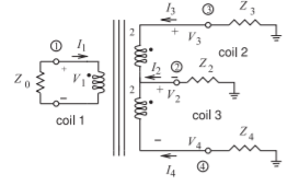
Figure \(\PageIndex{3}\)
- The balun of Figure 5.9.3 transforms an unbalanced system with a system impedance of \(Z_{0}\) to a balanced system with an impedance of \(4Z_{0}\). The actual impedance transformation is determined by the number of windings of the coils. Design a balun of the type shown in Figure 5.9.3 that transforms an unbalanced \(50\:\Omega\) system to a balanced \(377\:\Omega\) system. [Hint: Find the ratio of the windings of the coils.]
- A balun can be realized using a wire-wound transformer, and by changing the number of windings on the transformer it is possible to achieve impedance transformation as well as balanced-to-unbalanced functionality. A \(500\text{ MHz}\) balun based on a magnetic transformer is required to achieve impedance transformation from an unbalanced impedance of \(50\:\Omega\) to a balanced impedance of \(200\:\Omega\). If there are \(20\) windings on the balanced port of the balun transformer, how many windings are there on the unbalanced port of the balun?
- Design a lumped-element two-way power splitter in a \(75\:\Omega\) system at \(1\text{ GHz}\). Base your design on a Wilkinson power divider.
- Design a three-way power splitter in a \(75\:\Omega\) system. Base your design on a Wilkinson power divider using transmission lines and indicate lengths in terms of wavelengths.
- Design a lumped-element three-way power splitter in a \(75\:\Omega\) system at \(1\text{ GHz}\). Base your design on a Wilkinson power divider.
- A resistive power splitter is a three-port device that takes power input at Port \(\mathsf{1}\) and delivers power at Ports \(\mathsf{2}\) and \(\mathsf{3}\) that are equal; that is, \(S_{21} = S_{31}\). However, the sum of the power at Ports \(\mathsf{2}\) and \(\mathsf{3}\) will not be equal to the input power due to loss. Design a \(75\:\Omega\) resistive three-port power splitter with matched inputs, \(S_{11} =0= S_{22} = S_{33}\). That is, draw the resistive circuit and calculate its element values.
- Design a balun based on a magnetic transformer if the balanced load is \(300\:\Omega\) and the unbalanced impedance is \(50\:\Omega\).
- Draw the schematic of the balun with the load and indicate the ratio of windings.
- If the number of windings on the unbalanced side of the transformer is \(20\), how many windings are on the unbalanced side?
- Develop the electrical design of a rat-race hybrid at \(30\text{ GHz}\) in a \(50\:\Omega\) system.
- Develop the electrical design of a rat-race hybrid at \(30\text{ GHz}\) in a \(100\:\Omega\) system.
- Design a lumped-element \(180^{\circ}\) hybrid at \(1900\text{ MHz}\) using \(1\text{ nH}\) inductors.
- Design a \(90^{\circ}\) lumped-element hybrid at \(1900\text{ MHz}\) using \(1\text{ nH}\) inductors.
- Design a \(90^{\circ}\) lumped-element hybrid at \(500\text{ MHz}\) for a \(75\:\Omega\) system.
- Design a lumped-element \(180^{\circ}\) hybrid at \(1900\text{ MHz}\) matched to \(50\:\Omega\) source and load impedances.
5.16.1 Exercises by Section
\(†\)challenging, \(‡\)very challenging
\(§5.1\: 1\)
\(§5.2\: 2, 3, 4, 5\)
\(§5.5\: 6†, 7†, 8, 9, 10†\)
\(§5.8\: 11†, 12†\)
\(§5.9\: 13†, 14†, 15†, 16†, 17‡\)
\(§5.10\: 18†, 19†\)
\(§5.11\: 20†, 21†, 22†\)
\(§5.12\: 23†\)
\(§5.13\: 24‡, 25†, 26†, 27, 28, 29, 30\)
5.16.2 Answers to Selected Exercises
- \(12.57\)
- \(R_{1}=R_{2}=74.5\:\Omega\)
- \(75.48\:\Omega\)
- \(4.95\text{ W}\)
- (c) \(0.6\)
- \(-0.6897\)
- \(10\text{ dBm}\)
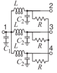
Figure \(\PageIndex{4}\)
\(L=20.7\text{ nH}\), \(C_{1}=3.68\text{ pF}\)
\(C_{2}=1.23\text{ pF}\), \(R=75\:\Omega\)
- ratio of windings is \(2.45\)
- Fig 5.13.3(a)
\(L=5.92\text{ nH}\), \(C=1.19\text{ pF}\)