
4.4: Multimoding on Transmission Lines
- Page ID
- 41039

Multimoding is a phenomenon that affects the integrity of a signal as it travels on a transmission line. For transmission lines, multimoding occurs when there are two or more EM field configurations that can support a propagating wave. Different field configurations travel at different speeds so that the information traveling in two or modes modes would combine incoherently and, if the energy in the modes is comparable, it will be impossible to discern the intended information being sent. It is critical that the dimensions of transmission line structures be designed to avoid multimoding. The most common mode on a transmission line is when there is no, or the minimum possible, variation of the fields in the transverse direction (perpendicular to the direction of propagation).
The transmission structures of interest here are those that have conductors that establish boundary conditions to guide a wave along an intended path. For these lines the lowest-order mode with minimum transverse field variations is called the TEM mode. Higher-order modes occur when the fields can vary. From here the discussion necessarily invokes EM theory. If you need to do this, see Section 1.5, where EM theory is reviewed specifically with respect to multimoding. One of the important concepts is that electric and magnetic walls impose boundary conditions on the fields. Electric walls are conductors, whereas a magnetic wall is formed approximately at the interface of two regions having different permittivity.
It is the property of EM fields that spatial variations of the fields cannot occur too quickly. This comes directly from Maxwell’s equations that relate the spatial derivative (the derivative with respect to distance) of the electric field to the time derivative of the magnetic field. The same is true for spatial variation of the magnetic field and time variation of the electric field. How fast a field varies with time depends on frequency. How fast an EM field changes spatially, its curl, depends on wavelength relative to geometry and on boundary conditions. Without electric and magnetic walls establishing boundary conditions, as in free space, a full wavelength is required to obtain the lowest-order variation of the fields. With electric or magnetic walls where the fields can terminate, a smaller distance is sufficient. Between two electric walls one-half wavelength of distance is required. The same is true for magnetic walls. With one electric wall and one magnetic wall, a quarter-wavelength separation of the walls will support a higher-order mode. A
| E field | H field | |
|---|---|---|
| Electric wall | Normal | Parallel |
| Magnetic wall | Parallel | Normal |
Table \(\PageIndex{1}\): Properties of the EM fields at electric and magnetic walls.
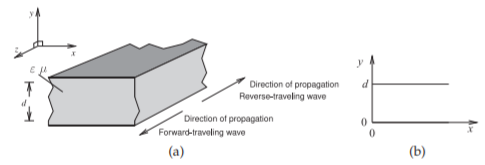
Figure \(\PageIndex{1}\): Parallel-plate waveguide: (a) three-dimensional view; and (b) cross-sectional (transverse) view.
general rule for avoiding multimoding is that critical transverse geometries must be kept to under a fraction of a wavelength (say, \(<\lambda/2\) or \(<\lambda/4\)).
One type of multimoding has already been described. In the previous chapter it was seen that the signals on a regular transmission line have two simple solutions that are interpreted as the forward-traveling and backward-traveling modes. Each mode is a possible solution of the differential equations describing the signals. These are not the modes being referred to by the term multimoding. The boundary conditions in the longitudinal direction are established by the source and load impedances, and so the variation can be any fraction of a wavelength. This section is concerned with other solutions to the equations describing the fields on a transmission line structure. In general, the other solutions arise when the transverse dimensions, such as the distance between the two conductors of a two-conductor transmission line, permits a variation of the fields.
The boundary conditions established at electric and magnetic walls were derived in Section 1.8 and are summarized in Table \(\PageIndex{1}\). Circuit structures such as transmission lines, substrate thicknesses, and related geometries are nearly always chosen so that only one solution of Maxwell’s equations is possible. In particular, if the cross-sectional dimensions of a transmission line are much less than a wavelength then it will be impossible for the fields to curl up on themselves and so perhaps there will be only one or, in some cases, no solutions to Maxwell’s equations.