Engineering LibreTexts

4.1: Introduction

  • Page ID
    41036
  • \( \newcommand{\vecs}[1]{\overset { \scriptstyle \rightharpoonup} {\mathbf{#1}} } \) \( \newcommand{\vecd}[1]{\overset{-\!-\!\rightharpoonup}{\vphantom{a}\smash {#1}}} \)\(\newcommand{\id}{\mathrm{id}}\) \( \newcommand{\Span}{\mathrm{span}}\) \( \newcommand{\kernel}{\mathrm{null}\,}\) \( \newcommand{\range}{\mathrm{range}\,}\) \( \newcommand{\RealPart}{\mathrm{Re}}\) \( \newcommand{\ImaginaryPart}{\mathrm{Im}}\) \( \newcommand{\Argument}{\mathrm{Arg}}\) \( \newcommand{\norm}[1]{\| #1 \|}\) \( \newcommand{\inner}[2]{\langle #1, #2 \rangle}\) \( \newcommand{\Span}{\mathrm{span}}\) \(\newcommand{\id}{\mathrm{id}}\) \( \newcommand{\Span}{\mathrm{span}}\) \( \newcommand{\kernel}{\mathrm{null}\,}\) \( \newcommand{\range}{\mathrm{range}\,}\) \( \newcommand{\RealPart}{\mathrm{Re}}\) \( \newcommand{\ImaginaryPart}{\mathrm{Im}}\) \( \newcommand{\Argument}{\mathrm{Arg}}\) \( \newcommand{\norm}[1]{\| #1 \|}\) \( \newcommand{\inner}[2]{\langle #1, #2 \rangle}\) \( \newcommand{\Span}{\mathrm{span}}\)\(\newcommand{\AA}{\unicode[.8,0]{x212B}}\)

    Previous chapters discussed the low-frequency operation of transmission lines. This chapter describes the origins of, particularly of planar lines. Figure \(\PageIndex{1}\) shows the typical frequency dependence of a line’s \(RLGC\) parameters. The variations of \(R\), \(L\), and \(C\) are of most interest, and, except with some semiconductor substrates, \(G\) is usually negligible.

    The major limitation on the dimensions and maximum operating frequency of a transmission line is determined by the origination of higher-order modes (i.e., orientations of the fields). Different modes on a transmission line travel at different velocities. Thus the problem is that if a signal on a line is split between two modes, then the information sent from one end of the line will reach the other end in two packets arriving at different times. The two modes have random partitioning of the signal

    clipboard_e17cddae81162eda69a885ab6e5925ecb.png

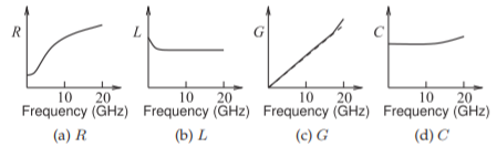
    Figure \(\PageIndex{1}\): Frequency dependence of transmission line parameters.

    clipboard_e92a46d5d6b8ef22c0110cacc3caeba8f.png

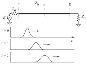
    Figure \(\PageIndex{2}\): Dispersion of a pulse along a line.

    energy and it is the combination that will be detected, and in general the information will be lost as the two modes combine in an incoherent manner. Multimoding must always be avoided.


    This page titled 4.1: Introduction is shared under a CC BY-NC license and was authored, remixed, and/or curated by Michael Steer.

    • Was this article helpful?