
5.12: Summary
- Page ID
- 41051

Coupling from one transmission line to a nearby neighbor may often be undesirable. However, the coupling can be controlled and coupled lines have become an important circuit component in distributed microwave circuits. One example is a directional coupler, which is little more than a pair of coupled lines, and this device forms the special function of separating forward- and backward-traveling waves. Another example of the application of coupled lines is their use in microwave filters. Bandpass filters are essentially coupled resonators. In a filter that uses coupled lines, each individual line becomes a resonator and the coupling of the resonators is controlled by how far they are spaced.
The analysis and circuit model of a pair of coupled lines is based on describing the voltages and currents on the lines as the linear combination of an even mode and an odd mode. Each of these modes will have forward- and backward-traveling wave components. Separating the signals on a coupled-line pair into even and odd modes facilitates extraction of the coupled-line parameters from simulation and measurement. It also enables a model of the coupled line to be developed that consists of individual lines that are coupled by transformers.
With the differential circuits used with RFICs it is more convenient to consider the signals on a pair of coupled lines as comprising common and differential modes. These can be directly related to even and odd modes and the difference comes down to definitions of average voltage (i.e., the common- and even-mode voltages) and the definition of the difference voltage (i.e., the differential- and odd-mode voltages). There is a similar difference for the currents.
The suite of microwave elements that exploit distributed effects available to a microwave designer is surprisingly large. Coupled lines comprise a large proportion of these elements. This chapter concludes with an example of the broadband response of a pair of coupled microstrip lines.
 Design Environment Project File: RFDesign Coupled Shorted Microstrip Lines.emp
In this example a pair of shorted coupled microstrip lines are examined using EM analysis. The layout of the coupled lines is shown in Figure \(\PageIndex{1}\). The box used in simulation has electric side and top walls. The bottom of the box (below the strips) is an electric wall and forms the ground plane. The ground plane is specified as gold and the finite conductivity of gold is used for the strips and the ground plane. The coupled lines here are arranged as a two-port structure. Scattering \((S)\) parameters are used to describe the characteristics of microwave structures. The transmission coefficient is \(S_{21}\), and for a matched structure \(S_{11}\) is the reflection coefficient. The coupled-line structure is symmetrical, as the widths of the strips are the same so that \(S_{11} = S_{22}\) and \(S_{12} = S_{21}\). Each microstrip line on its own was designed to have a characteristic impedance of \(50\:\Omega\).
The calculated two-port S parameters are plotted in Figure \(\PageIndex{2}\). The loss of \(0\text{ dB}\) corresponds to an \(S\) parameter absolute value of \(1\). Large \(S_{21}\) responses are centered at \(1.5\text{ GHz},\: 7.5\text{ GHz},\) and \(13\text{ GHz}\) and are shaped as bandpass filter responses. This suggests that coupled-line sections could be used as the basis of microwave bandpass filters. The passband frequencies are related to the lengths of the lines. The effective dielectric constant for one of the microstrip lines is \(6.5\) (from Table 3.5.1) and so at \(1.5\text{ GHz}\) the \(1\text{ cm}\) line length is \(\lambda/8\) long, at \(7.5\text{ GHz}\) it is \(5\lambda/8\) long, and at \(13\text{ GHz}\) it is \(9\lambda/8\) long. The round-trip lengths are \(\lambda/4,\: 5\lambda /4,\) and \(9\lambda /4\) long at the respective frequencies. Thus the round-trip lengths are separated by \(\lambda\) and so the addition of half-wavelength sections of lossless line has no impact on the reflection and transmitted response amplitudes.
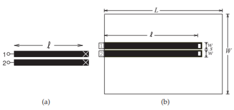
Figure \(\PageIndex{1}\): Coupled microstrip line layout: (a) schematic; and (b) layout in an EM field solver. Dimensions of the coupled lines are \(w = 500\:\mu\text{m},\: s = 100\:\mu\text{m},\:\ell = 1\text{ cm},\: W = 6\text{ mm},\: L = 12\text{ mm}\). The metal is \(6\:\mu\text{m}\) thick gold (conductivity \(\sigma = 42.6\times 10^{6}\)) and the alumina substrate height is \(600\:\mu\text{m}\) with relative permittivity \(\varepsilon_{r} = 9.8\) and a loss tangent of \(0.001\).
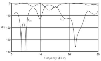
Figure \(\PageIndex{2}\): Insertion loss \((S_{21})\) and return loss \((S_{11})\) of the coupled line of Figure \(\PageIndex{1}\).