
5.14: Exercises
- Page ID
- 41053

\( \newcommand{\vecs}[1]{\overset { \scriptstyle \rightharpoonup} {\mathbf{#1}} } \) \( \newcommand{\vecd}[1]{\overset{-\!-\!\rightharpoonup}{\vphantom{a}\smash {#1}}} \)\(\newcommand{\id}{\mathrm{id}}\) \( \newcommand{\Span}{\mathrm{span}}\) \( \newcommand{\kernel}{\mathrm{null}\,}\) \( \newcommand{\range}{\mathrm{range}\,}\) \( \newcommand{\RealPart}{\mathrm{Re}}\) \( \newcommand{\ImaginaryPart}{\mathrm{Im}}\) \( \newcommand{\Argument}{\mathrm{Arg}}\) \( \newcommand{\norm}[1]{\| #1 \|}\) \( \newcommand{\inner}[2]{\langle #1, #2 \rangle}\) \( \newcommand{\Span}{\mathrm{span}}\) \(\newcommand{\id}{\mathrm{id}}\) \( \newcommand{\Span}{\mathrm{span}}\) \( \newcommand{\kernel}{\mathrm{null}\,}\) \( \newcommand{\range}{\mathrm{range}\,}\) \( \newcommand{\RealPart}{\mathrm{Re}}\) \( \newcommand{\ImaginaryPart}{\mathrm{Im}}\) \( \newcommand{\Argument}{\mathrm{Arg}}\) \( \newcommand{\norm}[1]{\| #1 \|}\) \( \newcommand{\inner}[2]{\langle #1, #2 \rangle}\) \( \newcommand{\Span}{\mathrm{span}}\)\(\newcommand{\AA}{\unicode[.8,0]{x212B}}\)
- Consider the cross section of a coupled transmission line, as shown in Figure 5.2.1, with even and odd modes both traveling out of the page.
- For an even mode on the coupled line, consider a phasor voltage of \(1\text{ V}\) on each of the lines above the ground plane at \(0\text{ V}\). Sketch the directed electric field in the transverse plane, i.e. show the direction of the electric field.
- For the even mode, sketch the directed magnetic fields in the transverse plane (the plane of the cross section).
- For an odd mode on the coupled line, consider a phasor voltage of \(+1\text{ V}\) on the left line and a phasor voltage of \(−1\text{ V}\) on the right line. Sketch the directed electric fields in the transverse plane (the plane of the cross section).
- For the odd mode, sketch the directed magnetic fields in the transverse plane (the plane of the cross section).
- EM software can be used to determine the even-and odd-mode parameters of a coupled line. This is usually done by setting the phasor voltage on the coupled line and evaluating the phasor charge for each condition. The voltage applied to the left strip is \(V_{1}\) and the voltage applied to the right strip is \(V_{2}\). The phasor charges on the strips are \(Q_{1}\) and \(Q_{2}\), respectively. The analysis is repeated with the substrate replaced by free space. In this case, the charges are denoted by \(Q_{01}\) and \(Q_{02}\). The (computer-based) measurements follow. [Parallels Example 5.5.1]
Charge \(V_{1}=1\text{ V}\);
\(V_{2}=-1\text{ V}\)\(V_{1}=1\text{ V}\);
\(V_{2}=1\text{ V}\)\(Q_{1}\) \((\text{pC/m})\) \(40\) \(20\) \(Q_{2}\) \((\text{pC/m})\) \(-50\) \(30\) \(Q_{01}\) \((\text{pC/m})\) \(13.25\) \(6\) \(Q_{02}\) \((\text{pC/m})\) \(-10\) \(2.75\)
Table \(\PageIndex{1}\)- What is the two-port capacitance matrix?
- What is the even-mode capacitance?
- What is the odd-mode capacitance?
- What is the free-space (no dielectric) two-port capacitance matrix?
- What is the free-space even-mode capacitance?
- What is the free-space odd-mode capacitance?
- What is the even-mode effective relative permittivity?
- What is the odd-mode effective relative permittivity?
- Two \(50\:\Omega\) microstrip lines are to be run parallel to each other on a \(1\text{ mm}\)-thick printed circuit board with a relative permittivity \(\varepsilon_{r} = 4\). The signal on the lines is \(3\text{ GHz}\). The effective permittivity of the lines is \(3.1\) and it is determined that the approximate distance over which the lines will be parallel is \(1.42\text{ cm}\). The coupling of the signals on the lines must be at least \(30\text{ dB}\) down.
- What is the free-space wavelength, \(\lambda_{0}\), of the signal?
- What is the guide wavelength, \(\lambda_{g}\), of the signal?
- How long is the parallel run of the microstrip lines in terms of \(\lambda_{g}\)?
- What is the required maximum parallel-line coupling factor? Explain your reasoning.
- What is the minimum separation of the lines? Explain your reasoning.
- A pair of coupled lines has an even-mode effective permittivity, \(\varepsilon_{ee}\), of \(4.9\) and an odd-mode effective permittivity of \(5.2\).
- What is the even-mode phase velocity?
- What is the odd-mode phase velocity?
- A directional coupler using coupled lines is constructed on an alumina substrate of thickness \(300\:\mu\text{m}\) and \(\varepsilon_{r} = 10\). The lines are \(250\:\mu\text{m}\) wide and the gap separation is \(100\:\mu\text{m}\). What are (a) the characteristic impedances, (b) the effective permittivities, and (c) the phase velocities of the even and odd mode of the coupled line. (Hint: If you use a table you need to use interpolation as described in Section 1.A.12.)
- An ideal directional coupler is lossless and there are no reflections at the ports. If the coupling factor is \(10\), what is the the magnitude of the transmission coefficient?
- A directional coupler has the following characteristics: coupling factor \(C = 20\), transmission factor \(0.9\), and directivity factor \(25\text{ dB}\). Also, the coupler is matched so that there is no reflection at any of the ports. What is the isolation in decibels?
- A lossy \(6\text{ dB}\) directional coupler is matched so that there is no reflection at any of the ports. The insertion loss (considering the through path) is \(2\text{ dB}\). If \(1\text{ mW}\) is input to the directional coupler, what is the power in microwatts dissipated in the directional coupler? Ignore power leaving the isolated port.
- A \(1\text{ GHz}\) microstrip directional coupler has a coupling factor of \(20\text{ dB}\). The coupler must have a system impedance of \(50\:\Omega\).
- Draw the layout of the directional coupler.
- What is the even-mode impedance of the coupler?
- What is the odd-mode impedance of the coupler?
- What is the optimum electrical length of the directional coupler in degrees at the design center frequency?
- If, in addition, the isolation of the directional coupler is \(40\text{ dB}\), what is its directivity in decibels?
- A directional coupler comprising a coupled pair of microstrip lines is to be designed in a \(75\:\Omega\) system. The coupling factor is \(10\).
- What is the system impedance \(Z_{0S}\)?
- What is the odd-mode impedance of the coupler?
- What is the even-mode impedance of the coupler?
- A matched directional coupler has a coupling factor \(C\) of \(20\), transmission factor \(0.9\), and directivity of \(25\text{ dB}\). What is the power dissipated in the directional coupler if the input power to Port \(\mathsf{1}\) is \(1\text{ W}\).
- Develop the design of a \(10\text{ dB}\) directional coupler using coupled microstrip lines and a substrate with a permittivity of \(10\), a substrate thickness, \(h\), of \(600\:\mu\text{m}\), and a center frequency of \(1\text{ GHz}\). Develop the electrical design of the coupler (i.e., find the even- and odd-mode impedances required) and then develop the physical design (with widths and lengths) of the directional coupler. Use a system impedance of \(50\:\Omega\).
- Design a microstrip directional coupler with the following specifications:
Transmission line technology: Microstrip
Coupling coefficient, \(C: 20\text{ dB}\)
Characteristic impedance, \(Z_{0S}\): \(50\:\Omega\)
Substrate permittivity, \(\varepsilon_{r}\): \(4.0\)
Substrate thickness, \(h\): \(635\:\mu\text{m}\)
Center frequency, \(f_{0}\): \(10\text{ GHz}\). - A directional coupler using coupled lines is constructed on an alumina substrate of thickness \(300\:\mu\text{m}\). The lines are \(250\:\mu\text{m}\) wide and the gap separation is \(100\:\mu\text{m}\). What are the characteristic impedances, effective permittivities, and phase velocities of the even- and odd-modes of the coupled line? Port \(\mathsf{1}\) is the input, Port \(\mathsf{2}\) is the through output, and Port \(\mathsf{3}\) is the coupled output. (Hint: See Table 5.8.3.)
- Draw the schematic of the directional coupler and label the ports.
- What is the transmission coefficient of the coupler?
- Can the directivity of the coupler be determined? If so, what is the directivity, \(D\), of the coupler?
- Consider a pair of parallel microstrip lines separated by a spacing, \(s\), of \(100\:\mu\text{m}\).
- What happens to the coupling factor of the lines as \(s\) reduces?
- What happens to the system impedance as \(s\) reduces and no other dimensions change?
- In terms of wavelengths, what is the optimum length of the coupled lines for maximum coupling?
- What is the coupling factor of a Lange coupler in decibels?
- Consider the open-circuited interdigital coupled-line section in Table 5.9.1. If the coupled line is \(\lambda/4\) long, write down the simplified \(ABCD\) parameters. Assume that \(\theta_{o} = \theta_{e}\).
- Consider the shorted symmetric coupled-line section in Table 5.9.1. If the coupled line is \(\lambda/4\) long, write down the simplified \(ABCD\) parameters. Assume that \(\theta_{o} =\theta_{e}\).
- Consider the open-circuited combine coupled-line section in Table 5.9.1. If the coupled line is \(\lambda/4\) long, write down the simplified \(ABCD\) parameters. Assume that \(\theta_{o} =\theta_{e}\).
- Consider the short-circuited interdigital coupled-line section in Table 5.9.1. If the coupled line is \(\lambda/4\) long, write down the simplified \(ABCD\) parameters. Assume that \(\theta_{o} =\theta_{e}\).
- A coupled microstrip line has an odd-mode impedance of \(30\:\Omega\) and an even-mode impedance of \(65\:\Omega\).
- What is the differential characteristic impedance of the coupled lines?
- What is the common-mode characteristic impedance of the coupled lines?
- A pair of coupled microstrip lines has odd- and even-mode characteristic impedances of \(60\:\Omega\) and \(70\:\Omega\) respectively. If a load resistance, \(R_{L}\), is placed at the end of the lines from one strip to the other, what is the value of \(R_{L}\) for no reflection of the even mode?
- The coupled lines below have odd- and even-mode characteristic impedances of \(30\:\Omega\) and \(60\:\Omega\) respectively.
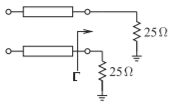
Figure \(\PageIndex{1}\)
- What is the odd-mode reflection coefficient \(\Gamma\)?
- What is the common-mode characteristic impedance of the coupled lines?
- The coupled lines below have odd- and even-mode characteristic impedances of \(60\:\Omega\) and \(100\:\Omega\) respectively. The coupled lines have a length \(\ell\) and this is \(\lambda/4\) long for the odd mode.
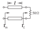
Figure \(\PageIndex{2}\)
- What is the odd-mode reflection coefficient at the load, call this \(\Gamma_{Lo}\)?
- What is the odd-mode reflection coefficient at the input to the coupled lines?
- The coupled microstrip lines below have an odd-mode characteristic impedance of \(40\:\Omega\) and an even-mode characteristic impedance of \(75\:\Omega\).
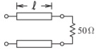
Figure \(\PageIndex{3}\)
- What is the differential-mode characteristic impedance?
- What is the common-mode characteristic impedance?
- The coupled lines below have odd- and even-mode characteristic impedances of \(40\:\Omega\) and \(75\:\Omega\) respectively.
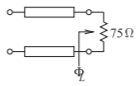
Figure \(\PageIndex{4}\)
- What is the differential-mode characteristic impedance, \(Z_{0d}\)?
- What is the differential-mode load resistance, \(Z_{Ld}\)?
- What is the differential-mode reflection coefficient, \(\Gamma_{Ld}\), at the load?
- What is the odd-mode reflection coefficient, \(\Gamma_{Ld}\), at the load?
- The coupled lines below have odd- and even-mode characteristic impedances of \(60\:\Omega\) and \(100\:\Omega\) respectively. The coupled lines have a length \(\ell\) and this is \(\lambda/4\) long for the odd mode.
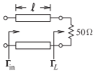
Figure \(\PageIndex{5}\)
- What is the differential-mode reflection coefficient, \(\Gamma_{d}\), at the load?
- What is \(\Gamma_{d}\) at the input of the lines?
5.14.1 Exercises by Section
\(†\)challenging, \(‡\)very challenging
\(§5.2\: 1†\)
\(§5.5\: 2†, 3‡\)
\(§5.6\: 4, 5,\)
\(§5.8\: 6, 7, 8, 9†, 10†, 11, 12†, 13†, 14†, 15†, 16\)
\(§5.9\: 17, 18, 19, 20\)
\(§5.10\: 21, 22, 23, 24, 25, 26, 27\)
5.14.2 Answers to Selected Exercises
- (h) \(3.87\)
- (c) \(v_{po}=1.256\cdot 10^{8}\text{ m/s}\)
- \(0.9950\)
- (b) \(187\text{ mW}\)
- (e) \(D=10\text{ dB}\)
- \(Z_{0e}=67.84\:\Omega\)
- \(C=2\jmath /(Z_{0e}-Z_{0o})\)
- \(32.5\:\Omega\)
- \(0.4118\)
- \(-0.0323\)