
1.1: Introduction to Microwave Modules
- Page ID
- 46059

Most microwave design develops microwave systems using modules such amplifiers, integrated circuits (ICs), filters, frequency multipliers, and passive components. Economics necessitate that since modules are expensive to design, e.g RF integrated circuits, that they be developed for multiple applications. In system design modules are chosen for their dynamic range, noise performance, DC power consumption, and cost. Foremost the system designer must have knowledge of available modules and be prepared to design a module itself if this results in competitive performance and manages cost. Modules are interconnected by transmission lines, bias settings and matching networks must be designed, and a system frequency plan must be developed that trades-off cost and performance while avoiding interference. All these topics are addressed on this book which develops the knowledge of modules, and the skills required to design microwave systems.
Most RF systems are composed of a cascade of modules each of which is separately designed and characterized. They often have \(50\:\Omega\) input and output impedances so that modules can be freely interconnected. Just as often matching networks must be design by the user as otherwise operating frequencies are pre-determined by the module vendor as a matching network usually has a narrower bandwidth than that of the functional core of the module. In high volume applications, several modules could be monolithically integrated, but even then, design is based on the concept of modules. Many modules are available “off the shelf” and high-performance RF systems can be constructed using them.
Examples of commercially available modules are shown in Figure \(\PageIndex{1}\). They can range in complexity from the surface mount resistor of Figure \(\PageIndex{1}\)(a) and the transformer of Figure \(\PageIndex{1}\)(d), up to the mixer and synthesizer modules shown in Figures \(\PageIndex{1}\)(b and c). Modules can have very good performance as it is cost effective to put considerable design effort into a module that can be used in many applications and thus design costs shared.
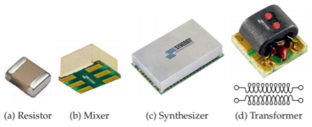
Figure \(\PageIndex{1}\): Modules in surface-mount packages. Copyright Synergy Microwave Corporation, used with permission [1].