
2.16: Case Study- Design of a Bandstop Filter
- Page ID
- 46082
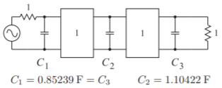
Figure \(\PageIndex{1}\): Bandpass filter approximation.
The design of a bandstop filter begins with the lowpass filter prototype shown in Figure \(\PageIndex{1}\). To the lowpass prototype, the highpass transformation is applied to obtain the highpass prototype of Figure \(\PageIndex{2}\). Picking a center frequency of approximately \(1\text{ GHz}\) and corner frequencies of \(f_{1} = 950\text{ MHz}\) and \(f_{2} = 1050\text{ MHz}\), corresponding to a bandwidth of approximately \(10\%\), the bandstop transformation is now applied. This results in the prototype of Figure \(\PageIndex{3}\). Finally, scaling the system impedance to \(50\:\Omega\) leads to the prototype of Figure \(\PageIndex{4}\). The impedance inverters must remain set at \(50\:\Omega\) in order to obtain a broad match. In the passband, energy will pass at all frequencies.
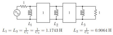
Figure \(\PageIndex{2}\): Bandstop filter prototype.
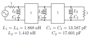
Figure \(\PageIndex{3}\): Bandstop filter following transformation from the lowpass prototype.
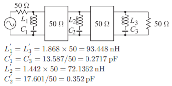
Figure \(\PageIndex{4}\): Bandstop filter after impedance transformation.
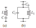
Figure \(\PageIndex{5}\): Transformations of the resonators in the bandstop filter to obtain realizable values. The series \(LC\) resonator in (a) is transformed to the form in (b).
In Figure \(\PageIndex{4}\), the inductor values are relatively large and the capacitor values are relatively small so that it will be difficult to realize the filter in either lumped or distributed forms. These values must be scaled to obtain realizable values. One possible transformation is shown in Figure \(\PageIndex{5}\). To establish that the left-hand and right-hand networks are equivalent, at least near one frequency, the impedances and derivatives must be matched. For the circuit in Figure \(\PageIndex{5}\)(a),
\[\label{eq:1}Z_{1}=\jmath\frac{\omega^{2}LC-1}{\omega C} \]
and
\[\label{eq:2}\frac{dZ_{1}}{d\omega}=\jmath\frac{\omega^{2}LC+1}{\omega^{2}C} \]
and for the circuit in Figure \(\PageIndex{5}\)(b),
\[\label{eq:3}Z_{2}=\jmath\frac{\omega^{2}L_{1}C_{1}-1+\omega^{2}L_{1}C_{0}}{\omega C_{0}(1-\omega^{2}L_{1}C_{1})} \]
and
\[\label{eq:4}\frac{dZ_{2}}{d\omega}=\jmath\frac{\omega^{4}L_{1}^{2}C_{1}^{2}-2\omega^{2}L_{1}C_{1}+\omega^{4}L_{1}^{2}C_{0}C_{1}+\omega^{2}L_{1}C_{0}+1}{\omega^{2}C_{0}(\omega^{2}L_{1}C_{1}-1)^{2}} \]
Equating the above enables \(C_{0}\) and \(C_{1}\) to be found for a chosen value of \(L_{1}\). Thus the series \(LC\) resonators in Figure \(\PageIndex{6}\)(a and c) are replaced by the
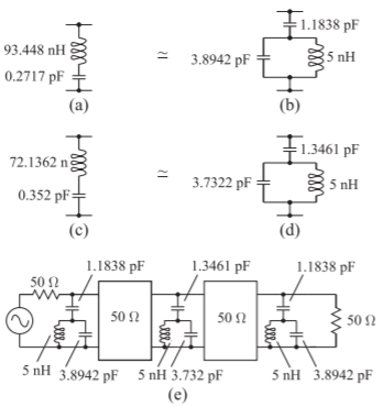
Figure \(\PageIndex{6}\): Intermediate bandstop filter prototype.
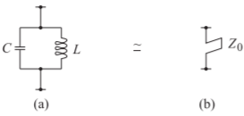
Figure \(\PageIndex{7}\): Equivalence of shunt bandpass resonator to shunt short-circuited stub.
networks in Figure \(\PageIndex{6}\)(b and d). This results in the filter of Figure \(\PageIndex{6}\)(e).
At this stage the bandpass resonators are then equated to short-circuited stubs by equating the admittance, \(Y_{1}\), of the lumped circuit in Figure \(\PageIndex{7}\)(a) with the admittance, \(Y_{2}\), of the stub in Figure \(\PageIndex{7}\)(b). That is, by equating
\[\label{eq:5}Y_{1}=\jmath\frac{(\omega^{2}CL-1)}{\omega L}\quad\text{and}\quad Y_{2}=\frac{1}{\jmath Z_{0}\tan\left(\frac{\pi}{2}\frac{\omega}{\omega_{r}}\right)} \]
The characteristic impedance of the stub, \(Z_{0}\), is selected so that the frequency, \(\omega_{r}\), is not too far above the upper band-edge frequency of the filter, in this case \(1.05\text{ GHz}\). Choosing \(Z_{0} = 20\:\Omega\) results in the stub transformations shown in Figure \(\PageIndex{8}\)(a–d). The bandstop filter prototype with stubs is shown in Figure \(\PageIndex{8}\)(e). The final physical layout of the bandstop filter is shown in Figure \(\PageIndex{9}\). The response of the final bandstop filter design is shown in Figure \(\PageIndex{10}\).
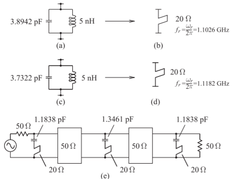
Figure \(\PageIndex{8}\): Bandstop filter prototype using stub approximations. The stub in (b) is the transmission line approximation of the parallel resonant circuit in (a). The stub in (d) approximates the circuit in (c).
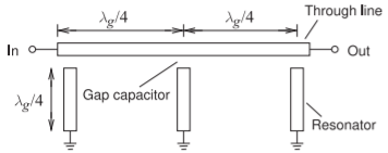
Figure \(\PageIndex{9}\): Physical layout of a bandstop filter in microstrip.
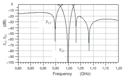
Figure \(\PageIndex{10}\): Response of the bandstop filter shown in Figure \(\PageIndex{9}\).