
2.18: Transient Response of a Bandpass Filter
- Page ID
- 46086
Figure \(\PageIndex{1}\): Lumped-element \(5\)th-order Chebyshev filter.
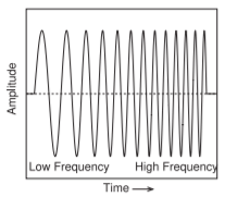
Figure \(\PageIndex{2}\): A linear chirp.
A bandpass filter is normally characterized by its center frequency and bandwidth, and sinusoidal signals that are within the bandwidth are transmitted by the filter and those outside the passband are reflected by the filter. However, if the signal changes frequency quickly, the transient response of the filter can be unexpected [32, 33].
Figure \(\PageIndex{1}\) is a fifth-order filter with each pair of shunt resonators coupled by a series resonator. In response to an RF pulse (a pulse of sinusoidally varying RF), the filter passes energy in-band when all of the resonators have reached steady state. When the RF pulse is removed, the resonators will loose energy and eventually the RF signals on the resonators disappear. There will be a finite time to “charge” and “discharge” the filter’s resonators.
A classic test of the RF response over frequency is to use a linear RF chirp, as shown in Figure \(\PageIndex{2}\). With a linear chirp, the frequency of the signal in the pulse changes linearly and smoothly over time from one frequency to another. Figure \(\PageIndex{3}\)(a) presents the transient response at the output of
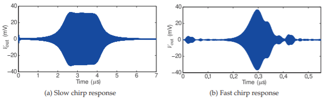
Figure \(\PageIndex{3}\): Output transient response of a 3rd-order Chebyshev filter with a center frequency of \(1\text{ GHz}\) and a \(30\text{ MHz}\) bandwidth excited by a \(−20\text{ dBm}\) linear chirp from \(950\text{ MHz}\) to \(1050\text{ MHz}\): (a) chirp rate \(= 20\text{ MHz/}\mu\text{s}\), (b) chirp rate \(= 400\text{ MHz/}\mu\text{s}\). At the slower chirp rate, the filter response is approximately a superposition of steady-state responses as the frequency changes (i.e., the response is quasi-stationary). At the higher chirp rate, the filter response can no longer be approximated as a sum of steady-state responses (i.e., it is no longer quasi-stationary). After [34].
a \(30\text{ MHz}\)-bandwidth \(1\text{ GHz}\) filter excited by a \(1\:\mu\text{s}\)-long linear chirp from \(950\text{ MHz}\) to \(1050\text{ MHz}\) with a chirp rate of \(20\text{ MHz/}\mu\text{s}\). This is a relatively slow chirp. The chirp starts at \(0\:\mu\text{s}\) and stops at \(5\:\mu\text{s}\). Thus the frequency of the chirp is in-band at \(1.75\:\mu\text{s}\) and is out-of-band at \(3.25\:\mu\text{s}\). The chirp is sufficiently slow that the transient transmission response corresponds to the frequency response of the filter. However, if the chirp is fast, the resonators may not reach steady state, and then the transient response of the filter cannot be simply extrapolated from its frequency-domain response. This is seen in Figure \(\PageIndex{3}\)(b), which is the response of the filter to a fast chirp with a chirp rate of \(400\text{ MHz/}\mu\text{s}\) and a chirp duration of \(250\text{ ns}\), and beginning at \(950\text{ MHz}\) and ending at \(1050\text{ MHz}\). The RF chirp begins out of band at \(0\text{ ns}\), becomes in-band at \(0.0875\:\mu\text{s}\), and goes out-of-band again at \(0.1625\:\mu\text{s}\) before turning off at \(0.25\:\mu\text{s}\). Interestingly, there is an almost immediate output response, around \(0.03\:\mu\text{s}\) when the RF chirp is out of band. Overall the chirped-filter response does not follow the frequency response of the filter.
Another view of the same phenomenon is examined for a \(7\)th-order Chebyshev filter with a center frequency of \(900\text{ GHz}\) and \(34\text{ MHz}\) bandwidth from \(883\text{ MHz}\) to \(917\text{ MHz}\). The frequency-domain transmission response of the filter is shown in Figure \(\PageIndex{4}\). The transmission responses to \(0.25\:\mu\text{s}\)-long RF pulses of different frequencies are shown in Figure \(\PageIndex{5}\). The frequency of the RF pulse is shown in each subplot. The top-left plot is the response when the RF pulse is in-band. Here the RF pulse is applied at \(0\:\mu\text{s}\) and removed at \(0.25\:\mu\text{s}\). An initial delay in the transmission response and what is referred to as a long-tail response is seen when the RF pulse is removed. The other plots in Figure \(\PageIndex{5}\) show the filter response as the RF is backed off from the passband. So, even when the RF is out of band, there can be an appreciable output from the filter at the beginning and end of the RF pulse.
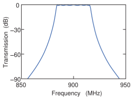
Figure \(\PageIndex{4}\): Frequency-domain transmission response of a \(7\)th-order Chebyshev filter with a center frequency of \(900\text{ GHz}\) and \(34\text{ MHz}\) bandwidth from \(883\text{ MHz}\) to \(917\text{ MHz}\).
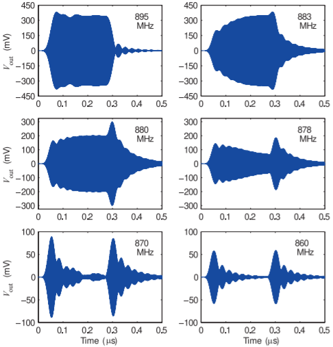
Figure \(\PageIndex{5}\): Transient response at the output of the \(900\text{ MHz}\) \(7\)th-order Chebyshev bandpass filter with a passband from \(883\text{ MHz}\) to \(917\text{ MHz}\). The frequency response is shown in Figure \(\PageIndex{4}\). After [34].