
7.7: Case Study- Frequency Planning of a Transceiver
- Page ID
- 46155
This case study develops the architecture and frequency plan of a transceiver for the licensed fixed wireless service in the \(15\text{ GHz}\) band that provides channels supporting up to \(140\text{ Mbit/s}\). This is the service that provides two-way point-to-point communications most commonly to connect pairs of cellular basestations to each other. A central basestation in a cluster of basestations then connects traffic into a backbone fiber optic-based network. Frequency planning begins with the specifications provided by national regulatory authorities which generally adopt recommendations from the International Telecommunications Union. (See [9] for the recommendations concerning the \(15\text{ GHz}\) fixed wireless service.)
The \(15\text{ GHz}\) fixed wireless band extends from \(14.4\text{ GHz}\) to \(15.35\text{ GHz}\) supporting a number of channels with various channel spacing. The spacing used will be based on local regulations and licensing. A universal transceiver must support channel spacings of \(2.5,\: 3.5,\: 7,\: 14,\: 28,\) and \(56\text{ MHz}\) [9]. Figure \(\PageIndex{1}\)(a) shows the channel assignment where \(f_{\text{CH}}\) is the channel spacing. No
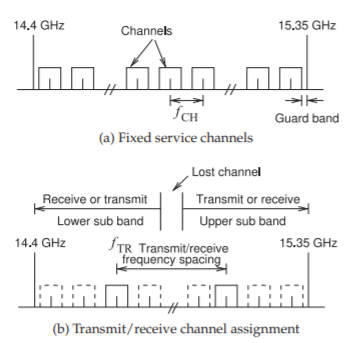
Figure \(\PageIndex{1}\): Channel assignment in the \(15\text{ GHz}\) fixed wireless service band.
guard bands between the channels are specified but typically a few \(10\)’s of kilohertz are sufficient. Thus channel spacing is only slightly larger than the modulation bandwidth and so there is a narrow guard band. Such a relatively tight guard band is possible as significant digital processing power can be used to resolve adjacent channels. At the low and high ends of the \(15\text{ GHz}\) band there is a guard band that is about half of a channel spacing so that other wireless services are not affected.
A transceiver in the fixed wireless service supports one or more transmit and receive channel pairs. As specification in the ITU regulations the separation of transmit and receive channel pairings can be \(315,\: 322,\: 420,\: 490,\: 640,\: 644,\: 728,\: 840\text{ MHz}\). That is, if a receive (or transmit) channel is centered at \(14.500\text{ GHz}\), then the paired transmit(or receive) channel is centered at \(14.815,\: 14.822,\: 14.920,\: 14.950,\: 15.140,\: 15.144,\: 15.228,\) or \(15.340\text{ MHz}\). Since a two-way link is established, the center frequency of the received channel at one end of the link is the center frequency of the transmitted channel at the other end of the link.
7.7.1 Transceiver Architecture
A transceiver must simultaneously transmit and receive channels and usually through the same antenna. Even if separate transmit and receive antennas are used, there will be significant coupling of the transmitted and received signal if they are located near each other. In practice transceivers use a diplex filter, a diplexer, to separate the \(15\text{ GHz}\) band into two sub bands of equal bandwidth. In principal a diplex filter can be two filters combined to provide a lowpass function for the upper sub band and a highpass filter for the lower sub band. For fixed wireless service operation the diplex filter is designed as two adjacent bandpass filters, one passing the lower sub band and the other passing the upper sub band. Although the filter skirts can be designed to be very steep, they necessarily have finite frequency extent so
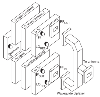
Figure \(\PageIndex{2}\): Transceiver architecture.
that the middle of the channel is no longer available to this transceiver.
The high-level architecture of a transceiver for the \(15\text{ GHz}\) fixed wireless service is shown in Figure \(\PageIndex{2}\). This architecture provides high isolation of the transmit and receive paths and supports a modular design approach. The transmit section comprises the three modules shown on the top of the figure. The first module is the transmit (Tx) digital baseband module that prepares the digitally modulated signal for one (or more) transmit channels. Either Reed-Solomon or trellis coded modulation (TCM) forward error correction schemes are used. Five modulation formats are typically supported: \(\text{QPSK, QAM16, QAM32, QAM64}\) or \(\text{QAM128}\) with the modulation scheme adjusted to maintain a maximum bit error rate of \(10^{−6}\). The signal in digital form is based in the transmit digital baseband module. The transmit analog baseband module modulates the signal on a carrier at an intermediate frequency of around \(1\text{ GHz}\). This is then passed to the transmit RF module which generates the RF signal in the \(15\text{ GHz}\) band. Typically the transmitted power is \(26\text{ dBm}\) using \(\text{QPSK}\) modulation, \(23\text{ dBm}\) using \(\text{QAM16,}\) \(22\text{ dBm}\) using \(\text{QAM32,}\) \(20\text{ dBM}\) using \(\text{QAM64}\), and \(19\text{ dBm}\) using \(\text{QAM128}\) modulation. The signal then passes into one port of the diplexer, here a waveguide diplexer, before passing to the antenna. The receiver sensitivity is typically \(−93\text{ dBm}\) for \(\text{QPSK}\), \(−86.5\text{ dBm}\) for \(\text{QAM16}\), \(−75\text{ dBm}\) for \(\text{QAM32}\), \(−73.5\text{ dBm}\) for \(\text{QAM64}\) modulation, and \(−68.5\text{ dBm}\) for \(\text{QAM128}\) modulation, again for a BER of better than \(10^{−6}\).
The waveguide diplexer is shown again in Figure \(\PageIndex{3}\). High performance diplexers can be designed in waveguide as there is very little loss and the \(Q\)s of the filter resonators are high [10, 11]. Here the waveguide diplexer has a bandpass response that passes the lower sub band, and a second bandpass response that passes the upper sub band. The sub band responses are shown in Figure \(\PageIndex{1}\)(b). The two bandpass responses are designed together so that the diplexer performance is better than if two independently designed bandpass filters were used. Either sub band output of the diplexer could be
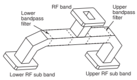
Figure \(\PageIndex{3}\): Waveguide diplexer with two bandpass filters inside the waveguide sections. One allows the lower RF sub band to pass and the other lets the upper sub band pass. The waveguide filter transition can be very sharp so that the edges of the upper and lower sub bands can be very close eliminating only one channel.
connected to the transmitter (and the other to the receiver) depending on whether the channel transmitted is in the lower or upper sub band.
The bottom three modules shown in Figure \(\PageIndex{2}\) comprise the receiver. The RF signal enters the Receiver (Rx) RF module at \(\text{RF}_{\text{IN}}\) where it is down converted to an intermediate frequency signal around \(1\text{ GHz}\). The intermediate signal passes to the Receive Analog Baseband module where the desired channel (or perhaps more than one) is extracted and presented to the receive digital baseband module at a frequency less than \(100\text{ MHz}\).
A common LO source is generated in the Reference LO module with one output connected by cables to the Receive RF module and another version of the LO, shifted by the appropriate receive/transmit frequency spacing, routed to the Transmit RF module.
The transmit and receiver RF and analog baseband modules must be mounted on the communication tower but the digital baseband and reference LO modules can be located in an air conditioned room. Then coaxial cables with signals up to \(2\text{ GHz}\) route the RF signals and the reference LO signals between the ground unit and the tower-mounted unit.
7.7.2 Frequency Planning
Basic frequency planning began with definition of the basic transceiver architecture with the choice of an intermediate frequency after first conversion (or before the final conversion in the case of the transmitter) that is around \(1\text{ GHz}\). This choice was made as the transceiver must be able to transmit across the entire \(950\text{ MHz}\) bandwidth of the \(15\text{ GHz}\) band. Once the orientation of the diplexer has been fixed before delivery to the customer, or in field installation, the transmit band is from one sub band to the other sub band, a narrower but still significant \(475\text{ MHz}\) bandwidth. However the unit must still be designed to support operation over the whole band. Thus, for the receiver, the design decision has been made to down convert an entire sub band to a frequency range centered around \(1\text{ GHz}\). Such a circuit must have essentially a lowpass response but with signals at DC and up to a hundred megahertz or so above blocked by inductors and capacitors providing DC connections and/or RF isolation. The fractional bandwidth is too much for the design of a bandpass filter. The frequency conversion description is similar for the transmitter.
Frequency planning has a major impact on the design cost of the transceiver and in the unit cost, especially if extensive tuning is required during manufacture. Frequency planning requires considerable experience with knowledge of design cost drivers, manufacturability, which modules and sub modules are available from vendors, and what one’s own organization can do to provide a competitive advantage. To be competitive
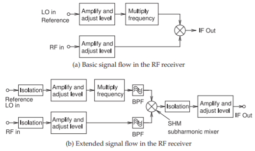
Figure \(\PageIndex{4}\): Signal paths in the receive RF module in Figure \(\PageIndex{2}\).
the transceiver must be tunable across the entire \(15\text{ GHz}\) band.
Cost is substantially reduced by sharing an LO between the transmitter and receiver, with either the transmit or receiver versions of the LO shifted by the appropriate transmit/receive spacing. The LO will be locked to a low frequency reference using a phase-locked loop and then it must be routed by coaxial cable to the receive and transmit RF modules. This means that LO should ideally be below \(2\text{ GHz}\). This LO will now be called the reference LO as it is not the ultimate frequency that is required by the mixer in the frequency conversion section of the receiver RF module. Ultimately the effective LO at the mixer must be tunable across the entire \(15\text{ GHz}\) band and so needs to tune at least by \(950\text{ MHz}\). Tuning can be accomplished using phase-locked loops but realistically the tuning range that can be conveniently achieved is \(200\text{ MHz}\) or \(15\%\), whichever is less up to \(2\text{ GHz}\).
The basic signal flow in the receiver RF module is shown in Figure \(\PageIndex{4}\)(a). The basic concept is that the received RF signal is mixed with an LO to produce a low frequency version as the intermediate frequency signal, the IF. In the signal flow, a typically low-level RF signal is presented to the receiver at the port indicated by \(\text{RF}_{\text{IN}}\). The RF signal is amplified by a low noise amplifier so that circuit noise in the following RF signal path has no impact. Since the level of the received signal is not known, the amplitude of the signal must be leveled. The reference LO is at a frequency below that required to pump the mixer so that it can be more easily generated and routed in the transceiver. Generally it would be preferable to keep the signals to be routed below \(2\text{ GHz}\) as then the quality of the cabling and connections is less critical. As a result the frequency of the reference LO signal must be increased before it is presented to the mixer.
Knowledge of which sub modules are readily available is also critical in frequency planning. The use of frequency multipliers, essentially nonlinear harmonic generators followed by filters, can increase the frequency by a factor of \(8\) or so quite reliably. With frequency multiplication there is an increase in the noise levels of the oscillator that impacts performance and
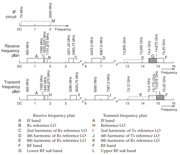
Figure \(\PageIndex{5}\): Transceiver frequency plan. The receive and transmit frequency plans are exchanged if the RF received is in the upper RF band (and then the RF transmitted is in the lower RF sub band. Also shown is the IF circuit bandwidth extending from \(70\text{ MHz}\) to \(2\text{ GHz}\).
this means that the noise performance of the reference LO needs to be that much better. Furthermore there is a need to adjust signal levels to avoid distortion. One of the essential characteristics of most module design is that modules can be freely interconnected without concern that one module will affect the operation of another module. To achieve this isolation is required. Another design choice is to use a subharmonic mixer in which the the pump frequency is about half of the RF frequency. The subharmonic mixer also has the property that very little of the second harmonic of the LO signal passes into the RF circuitry. It is very important that the range of frequencies in the LO path, the RF path, and the IF path do not overlap. With this knowledge the signal flow path in the receiver RF module can be extended as shown in Figure \(\PageIndex{4}\)(b).
Using the above considerations and also considering the transmit requirements leads to the detailed frequency plan shown in Figure \(\PageIndex{5}\). This plan is arrived at iteratively considering design and unit cost, as well as the required time to market. While Figure \(\PageIndex{5}\) shows the receiver using the lower sub band and the transmitter using the upper side bands, this sub band allocation could be reversed and this is achieved by simply switching the diplexer sub band ports, i.e. by rotating the waveguide diplexer.
7.7.3 Summary
Once the frequency plan has been established the design of the individual modules can proceed independently. The final receiver RF module was shown in Figures 7.6.1 and 7.6.2 with the block diagram of the module shown in Figure 7.6.3.
Frequency planning may seem rather simple but it is more than drawing a spectral diagram such as that in Figure \(\PageIndex{5}\). The architecture of the transceiver is defined along with the frequency plan. Thus frequency planning is done by experienced engineers with a broad appreciation for RF system performance, knowledge of available off-the-shelf modules, appreciation for cost, and appreciation for what it takes to develop a competitive product. Frequency planning has a tremendous impact on system cost. The final system design has a value far exceeding the cost of the component sub modules.