
1.5: Conventional Wireless Communications
- Page ID
- 41167

Up until the mid-1970s most wireless communications were based on centralized high-power transmitters, often operating in a wide-area broadcast mode, and reception (e.g., by a television or radio unit) was expected until the signal level fell below a noise-related threshold. These systems are particularly sensitive to interference, therefore systems transmitting at the same frequency were geographically separated so that a transmitted signal falls below the background noise threshold before there
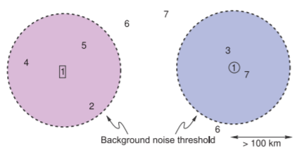
Figure \(\PageIndex{1}\): Interference in a conventional radio system. The two transmitters, \(\mathsf{1}\), are at the centers of the coverage circles defined by the background noise threshold.
is a chance of it interfering with a neighboring system operating at the same frequency. This situation is illustrated in Figure \(\PageIndex{1}\). Here there are a number of base stations, each operating at a frequency (or set of frequencies) designated by numerals referring to the frequency of operation, which are correspondingly designated as \(f_{1},: f_{2}\), etc. In Figure \(\PageIndex{1}\) the coverage by two base stations, \(\mathsf{1}\), both operating at the frequency \(f_{1}\) are shown by the shaded regions. The shading indicates the geographical region over which the signals are above the minimum detectable signal threshold. The frequency reuse factor of these types of systems is low, as there is a large geographical area where there is no reception at a particular frequency. The coverage area will not be circular or constant because terrain is not flat, signals are blocked by and reflected from buildings, and background noise levels vary during the day and signal levels vary from season to season as vegetation coverage changes. Allowances must be made in the allocation of broadcast areas to account for the changing coverage level. At the same time, it is necessary, in conventional radio, for the coverage area to be large so that reception, particularly for mobile devices, is continuous over metropolitan-size areas.
The original mobile radio service in the United States is now called 0G for zero-generation radio. Very few users could be supported in 0G mobile radio because there were very few channels. The first 0G mobile system, the Mobile Telephone Service introduced in 1946, had six channels. That is, only six calls could be made at any one time. Because of interference this was reduced to three channels. So a metropolitan area such as New York city could only support three calls at the same time. In the three-channel version, the channels were \(60\text{ kHz}\) wide and with a little more than \(60\text{ kHz}\) guard band between channels. More channels were eventually made available. However the maximum practical frequency at the time was \(450\text{ MHz}\) and the spectrum from \(1\text{ MHz}\) to \(500\text{ MHz}\) was highly sought after. Other uses included AM and FM radio, TV broadcast, military communications, and radar. It was seen by regulatory authorities that it was not in the public interest to support more individual users if that meant that broadcast services that catered to many people had to be compromised. There were no cells, just one large coverage area. In every change in radio generation there have been multiple enhancements to improve capacity. So just providing more bandwidth so there could be more channels was not a viable option. Supporting the transition to 1G was more bandwidth, the concept of cells and handoff, narrow channels, and higher operating frequency (\(900\text{ MHz}\) to \(1\text{ GHz}\)). The continued evolution to fifth generation (5G) radio and the concepts that supported it are described in Chapters 2–5.