
3.14: Modern Architectures
- Page ID
- 41200

This section discusses transmitter and receiver architectures in the generations before software defined radio (as used in 4G and 5G). These are architectures that could be implemented in analog hardware.
3.7.1 Receiver Architectures
It is more challenging to achieve a high performance for a receiver than it is for a transmitter.
or a transmitter. Communication receivers most commonly use mixing of the RF signal with a fixed signal called an LO to produce a lower-frequency replica of the modulated RF signal. Some receiver architectures use one stage of mixing, while others use two stages. In cellular systems, the receiver must be sensitive enough to detect signals of \(100\text{ fW}\) or less.
Some of the architectures used in modern receivers are shown in Figure \(\PageIndex{2}\). Figure \(\PageIndex{2}\)(a) is the superheterodyne architecture in much the same form that it has been used for a century. Key features of this architecture are that there are two stages of mixing, and filtering is required to suppress spurious mixing products. Each mixing stage has its own VCO. The receiver progressively reduces the frequency of the information-bearing signal. The image rejection mixer in the dashed box achieves rejection of the image frequency to produce an IF (or baseband frequency) that can be directly sampled. However, it is difficult to achieve the required amplitude and phase balance. Instead, the architecture shown in Figure \(\PageIndex{2}\)(b) is sometimes used. The filter between the two mixers can be quite large. For example, if the
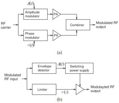
Figure \(\PageIndex{1}\): Polar modulator architectures: (a) amplitude- and phasemodulated components amplified separately and combined; and (b) the amplitude used to modulate a power supply driving a saturating amplifier with phase modulated input.
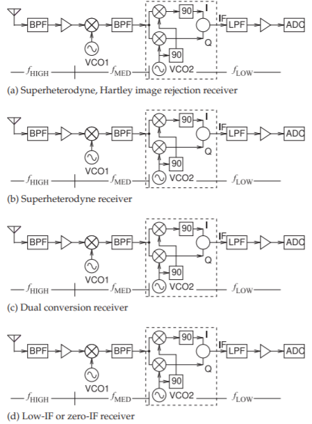
Figure \(\PageIndex{2}\): Architectures of modern receivers: (a) superheterodyne receiver using the Hartley architecture for image rejection; (b) superheterodyne receiver; (c) dual-conversion receiver; and (d) low-IF or zero-IF receiver. BPF, bandpass filter; LPF, lowpass filter; ADC, analogto-digital converter; VCO, voltage-controlled oscillator; \(90,\: 90^{\circ}\) phase shifter; \(f_{\text{HIGH}},\: f_{\text{MED}},\) and \(f_{\text{LOW}}\) indicate relatively high-, medium-, and low-frequency sections.
incoming signal is \(1\text{ GHz}\), the frequency of the signal after the first mixer could be \(100\text{ MHz}\).
Filters are smaller and have higher performance at higher frequencies. This is exploited in the dual-conversion receiver shown in Figure \(\PageIndex{2}\)(c). This is similar to the traditional superheterodyne architecture except that the IF between the two mixers is high. For example, if the incoming signal is \(1\text{ GHz}\), the output of the first mixer could be \(3\text{ GHz}\). This architecture also enables broad radio operation with the band selected by choosing the frequencies of the two local oscillators.
The low-IF or zero-IF receiver shown in Figure \(\PageIndex{2}\)(d) uses less hardware and is common in less demanding communication applications. In high performance systems, such as the cellular phone system, this architecture requires more design time as well as calibration circuitry to trim the I and Q paths so that they are closely matched.
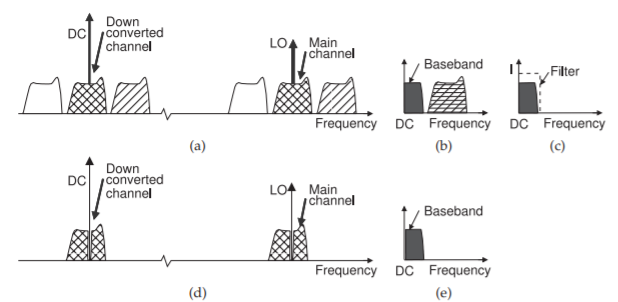
Figure \(\PageIndex{3}\): Frequency conversion using homodyne mixing: (a) the spectrum with a large LO and the low frequency products after down conversion; (b) the baseband spectrum showing only positive frequencies; (c) the baseband spectrum after mixing; (d) down conversion spectra when the radio signal has no spectral content at the carrier frequency; and (e) the lowpass filtered down-converted signal in (d).
3.7.2 Homodyne Frequency Conversion
Homodyne mixing and detection is one of the earliest wireless receiver technologies and is used in AM radio. In homodyne mixing, the carrier of a modulated signal is regenerated and synchronized in phase with the incoming carrier frequency. Mixing the carrier with the RF signal results in an IF signal centered around zero frequency.
The signal spectra in homodyne mixing is shown in Figure \(\PageIndex{3}\). In Figure \(\PageIndex{3}\)(a), the RF signals are shown on the right-hand side and the baseband signals are shown on the left-hand side. It is usual to show both positive and negative frequencies at the lower frequencies so that the conversion process is more easily illustrated. Of course negative frequencies do not exist. The characteristic of homodyne mixing is that the LO corresponds to the carrier and is in the middle of the desired RF channel. RF signal components mix with the LO, and it appears that the entire RF spectrum is down-shifted around DC. Of course, the actual baseband spectrum is only defined for positive frequencies, so the negative-frequency baseband signals and the positive-frequency baseband signals combine to yield the detected baseband spectrum shown in Figure \(\PageIndex{3}\)(b). With other modulation schemes, this possible loss of information is avoided using quadrature demodulation. An amplitude modulated signal has identical modulation sidebands, so the collapsing of positive and what is shown as negative frequencies at baseband results in no loss of information. Then a simple amplitude detection circuitry, such as a rectifier, is used and the rectified signal was (typically) passed directly to a speaker.
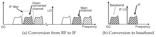
Figure \(\PageIndex{4}\): Frequency conversion using superheterodyne mixing.
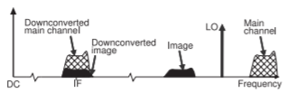
Figure \(\PageIndex{5}\): Frequency conversion using heterodyne mixing showing the effect of image distortion with the down-converted image overlapping the down-converted main channel.
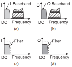
Figure \(\PageIndex{6}\): Frequency conversion using direct conversion quadrature mixing: (a) the baseband spectrum at the I output of the receiver; (b) the baseband spectrum at the Q output of the receiver; and (c and d) the spectrum of the I and Q channels following.
3.7.3 Heterodyne Frequency Conversion
In heterodyne mixing, the locally generated LO and the main RF channel are separated in frequency, as shown in Figure \(\PageIndex{4}\)(a). In this figure the RF signals (shown as three discrete channels on the right-hand side of the spectrum) mix with the LO to produce signals at a lower frequency. This lower frequency is usually not the final baseband frequency, and so is called the intermediate frequency (IF). The IF of the main channel is at the difference frequency of the RF signal and the LO. There are several important refinements to this. The first of these is concerned with limiting the number of signals that can mix with the LO. This is done using an RF preselect filter. To see the difficulties introduced by the image channel, consider the frequency conversion to an intermediate frequency described in Figure \(\PageIndex{5}\). Filtering reduces the level of the image channel as shown in Figure \(\PageIndex{5}\)(a). Note that the main channel and its image are equidistant from the LO, see Figure \(\PageIndex{5}\). Both down-convert to the same IF frequency. In the worst-case scenario, the IF image could be larger than that of the desired channel.
3.7.4 Direct Conversion Receiver
Zero-IF direct conversion receivers are similar to quadrature homodyne receivers in that the LO is placed near the center of the RF channel The important characteristic of direct conversion receivers is that there is only one level of mixing. The conversion process is described in Figure \(\PageIndex{6}\). A particular advantage of direct conversion is that the relatively large IF filters are eliminated. They are invariably implemented as quadrature
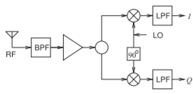
Figure \(\PageIndex{7}\): Direct conversion quadrature demodulator.
demodulators, see Figure \(\PageIndex{7}\). used in cellular phones as it uses uses little DC power, and hence extends battery life, and is compatible with monolithic ICs. Direct conversion is now the preferred method of down conversion.
The main nonideality of this design is the DC offset in the down-converted spectrum. DC offset results mostly from self-mixing, or rectification, of the LO. This DC offset can be much larger than the down-converted signal itself. One way of coping with the DC offset is to highpass filter the downconverted signal, but highpass filtering requires a large passive component (e.g., a series capacitor), at least to avoid the dynamic range problems of active filters. Highpass filtering the down-converted signal necessarily throws away information in the signal spectrum, and it is only satisfactory to do this if there is very little information around DC to begin with.
The primary design effort with zero-IF converters is overcoming the DC offset problem, and to a lesser extent coping with the jitter of the LO. However there is a scheme used in 4G and 5G that overcomes these limitations. This will be discussed in following chapters.
3.7.5 Low-IF Receiver
In a low-IF receiver, single-stage heterodyne mixing is used to down-convert the modulated RF carrier to a frequency just above DC, perhaps a few hundred kilohertz or a few megahertz, depending on the bandwidth of the RF channel. In doing this, the DC offset problem of a direct conversion receiver is avoided. This frequency offset can be just a few hundred hertz to be effective. Low IF conversion is now the preferred method of down-conversion in cellular phones as it requires very little batter usage, does not require large IF filters, and is compatible with monolithic ICs. Sometimes low-IF conversion is referred to as direct down conversion but there is a subtle difference.
3.7.6 Subsampling Analog-to-Digital Conversion
Subsampling receivers overcome the DC offset problem typical of other direct conversion receivers. The idea is to sample the modulated RF signal at a subharmonic of the carrier of the RF signal to be converted. The sampling rate must be at least twice the bandwidth of the baseband signal and the track-mode bandwidth must be greater than the carrier frequency. Thus the sampling aperture is the critical parameter and must be several times smaller than the period of the carrier. Fortunately the aperture times of CMOS tracking circuits are adequate. It is critical that an RF preselect filter be used to eliminate unwanted interferers and noise outside the communication band. Aliasing of signals outside the Nyquist bandwidth onto the baseband signal is a consequence of subsampling. Adjacent channel signals are converted without aliasing, but these will lie outside the bandwidth of the
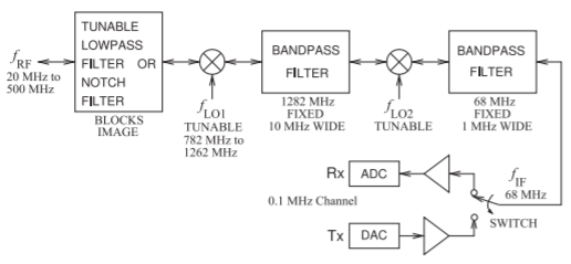
Figure \(\PageIndex{8}\): Bilateral double-conversion transceiver for wideband operation of an emergency or military radio.
baseband signal. Flicker noise on the sampling clock is multiplied by the subsampling ratio and appears as additional noise at baseband. This was at one time a very attractive option but has been out-performed by the low-IF receiver.
3.7.7 First IF-to-Basebind Conversion
In a superheterodyne conversion architecture there are two heterodyne stages, with the IF of the first stage in modern systems in the range of \(20\) to \(200\text{ MHz}\). The assignment of frequencies is known as frequency planning, and this is treated as proprietary by the major radio vendors. This IF is then converted to a much lower IF, typically around \(100\text{ kHz}\) to a few megahertz above the center frequency of the baseband signal. This frequency is generally called baseband, but strictly it is not because the signal is still offset in frequency from DC. Some direct conversion architectures leave the first heterodyne mixing stage in place and use direct conversion of the first IF to baseband (true baseband—around DC).
3.7.8 Bilateral Double-Conversion Receiver
The receivers considered so far are suitable for narrowband communications typical of point-to-point and consumer mobile radio. There are many situations where the range of received or transmitted RF signals covers a very wide bandwidth, such as with emergency radios, television, and military communications. Typically, however, the instantaneous bandwidth is small. If narrowband RF front-end architectures are used, a switchable filter bank would be required and this would result in an impractically large radio. One solution to covering very wide RF bandwidths is the double-conversion transceiver architecture shown in Figure \(\PageIndex{8}\). The frequency plan of a typical radio using \(0.1\text{ MHz}\) channels between \(20\text{ MHz}\) and \(500\text{ MHz}\) is shown. The key feature of this radio is that bidirectional mixers are used. Following the RF chain from left to right, the RF is first mixed up in frequency, bandpass filtered using a high-\(Q\) distributed filter, and then down-converted to a lower frequency that can be sampled directly by an ADC. A much higher performance passive (and hence bidirectional) filter can be realized at gigahertz frequencies than at a few tens of megahertz. On transmit, the function is similar, with the mixers and LO reused. As a receiver, the notch filter or lowpass filter is used to block the image frequency of the first mixer so that only the upper sideband IF is presented to the first bandpass filter. The lowpass or notch filter may be fixed, although, with the plan shown, there must be at least two states of the filters. On transmit, the lowpass or notch filters prevent the image frequency from being radiated.