
3.2: Single-Sideband and Double-Sideband Modulation
- Page ID
- 41188

The simplest implementation of analog modulation results in a modulated carrier signal whose spectrum consists of the carrier and upper and lower sidebands. It is possible to eliminate one of the sidebands in AM modulation, or one of the sidebands sets in PM and FM modulation, producing single sideband modulation SSB. This however needs to be implemented in DSP. At the same time the carrier can be suppressed resulting in suppressed-carrier modulation or together SSB-SC modulation.
The simplest system that implements SSC-SC modulation is the Hartley modulator [1, 2], shown in Figure 3.1.1. This circuit results in single-sideband (SSB) modulation or more precisely single-sideband modulation suppressed-carrier (SSB-SC) modulation. This circuit is used in all modern radios taking a modulated signal which is centered at an intermediate frequency and shifting it up in frequency so that its is centered at another frequency a little below or a little above the carrier of the Hartley modulator.
Both the modulating signal m(t)and the carrier are multiplied together in a mixer and then also \(90^{\circ}\) phase-shifted versions are also mixed before being added together. The signal flow is as follows beginning with \(m(t) = \cos(\omega_{m1}t),\: p(t) = \cos(\omega_{m1}t − π/2) = \sin(\omega_{m1}t)\) and carrier signal \(c_{1}(t) = \cos(\omega_{c}t)\):
\[\begin{align}a_{1}(t)&=\cos(\omega_{m1}t)\cos(\omega_{c}t)=\frac{1}{2}\left[\cos ((\omega_{c}-\omega_{m1})t)+\cos((\omega_{c}+\omega_{m1})t)\right] \nonumber \\ b_{1}(t)&=\sin(\omega_{m1}t)\sin(\omega_{c}t)=\frac{1}{2}\left[\cos((\omega_{c}-\omega_{m1})t)-\cos((\omega_{c}+\omega_{m1})t)\right]\nonumber \\ \label{eq:1} s_{1}(t)&=a_{1}(t)+b_{1}(t)=\cos((\omega_{c}-\omega_{m1})t)\end{align} \]
and so the lower sideband (USB) is selected.
That is, if a finite bandwidth modulating signal \(m(t)\) was mixed only once with the carrier \(c_{1}(t)\), the spectrum of the output \(a_{1}(t)\) would include upper and lower sidebands as well as the carrier as shown in Figure \(\PageIndex{1}\)(a). With the Hartley modulator the spectrum of Figure \(\PageIndex{1}\)(b) is obtained.
In digital modulation both the upper and lower sideband are retained but the carrier is suppressed. Both sidebands are required to recover the signal but the spectrum is used efficiently as the modulating signal is complex with two components, think of real/imaginary parts, or amplitude/phase information. Since a DSP unit is required the resulting modulated signal must be at a relatively low frequency and then a second frequency conversion stage is required to shift the modulated signal to the desired operating frequency, see Figure \(\PageIndex{2}\). This second stage is a SSB-SC modulator, however since the input to the second stage is a DSB-SC signal, the final RF signal is a DSB-SC signal.
All the concepts introduced in this section are still used in modern radios, just that now they are mostly implemented in a DSP unit rather than in analog hardware.
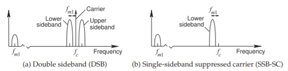
Figure \(\PageIndex{1}\): Spectrum of a modulated carrier with a modulating signal of finite bandwidth \(f_{m}\) with \(f_{m1}\) being the center frequency of the baseband signal.
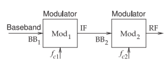
Figure \(\PageIndex{2}\): Two-stage modulator with the baseband signal, BB1, input to the first modulator, Mod1, producing the intermediate frequency signal \(\text{IF}_{1}\). This becomes the baseband signal, \(\text{BB}_{2}\), for the second modulator, \(\text{Mod}_{2}\), producing the radio frequency signal, RF.