
3.9: SDR Receiver
- Page ID
- 41195

An SDR receiver implements the demodulation shown in Figure 3.10.24(a) in two stages with analog RF quadrature demodulation in the first stage similar to that shown in Figure 3.10.24(b). There is a lot of detail in this section but this is required to understand the implementation of an SDR receiver at the level of design.
The block diagram of a particular implementation of an SDR receiver is shown in Figure \(\PageIndex{1}\) which has a first stage in the analog domain implemented in an RF modem chip, and a second digital stage that is implements DSP in the baseband chip. While these are separate chips at the time of this writing they will probably be combined in a single chip someday.
The analog portion of the SDR receiver is shown in Figure \(\PageIndex{1}\). This first stage separates the I and Q channels and outputs baseband frequency signals that are sampled and input to a second stage of quadrature demodulation to produce the final baseband signals. This second stage is implemented digitally. The signals at the output of the first analog stage are also called intermediate frequencies. Digital demodulation, on the right in Figure \(\PageIndex{1}\), is performed in a DSP unit commonly referred to as a baseband modem chip. A key attribute is that the LO frequency of the first demodulation stage, \(f_{\text{LO}}\) can be set at relatively few discrete values while the LO in the second stage, \(f_{\text{LO, IF}}\) is set finely for full carrier recovery. Together \(f_{\text{LO}} + f_{\text{LO, IF}} = f_{c}\), the frequency of the carrier of the received signal \(s(t)\). The DSP unit can implement decoding such as CDMA- or OFDM-decoding.
The rest of this section traces the signal flow through the SDR receiver. The signal presented to the demodulator is \(G_{L}s(t)\) where \(s(t)\) is the transmitted DSB-SC signal in Equation (3.9.1). \(G_{L}\), which will be very small, is the link gain accounting for loss in transmission and receiver gain and, in the absence
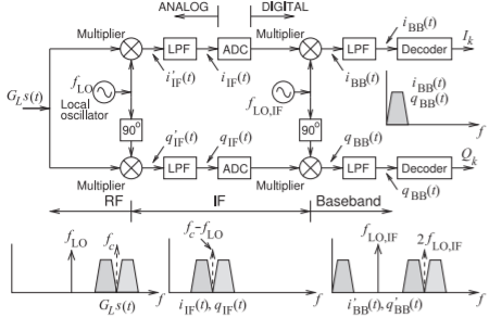
Figure \(\PageIndex{1}\): SDR receiver with RF input signal \(G_{L}s(t)\) with the first LO frequency, \(f_{\text{LO}}\), less than the carrier signal \(f_{c}\). Note that \(2f_{\text{LO, IF}} = f_{c} − f_{\text{LO}}\).
of interference, \(s(t)\) is the transmitted radio signal.
3.12.1 Demodulation of the I component
If the transmitted signal is the DSB-SC signal \(s(t)\) with carrier \(f_{c}\) in Equation (3.9.1) (replacing \(\omega_{\text{LO}}\) by \(f_{c}\)) then the signal presented to the demodulator in the receiver is \(G_{L}s(t)\) where \(G_{L}\), which will be very small, is the link gain accounting for loss in transmission and receiver gain. The spectrum of the received DSB-SC signal, \(G_{L}s(t)\), is shown on the bottom left of Figure \(\PageIndex{1}\) with the carrier frequency \(f_{c}\) identified by the dash arrow. The LO frequency of the first demodulator at \(f_{\text{LO}}\) is also shown. The in-phase component of the demodulated signal after the first quadrature demodulator is, see Figure \(\PageIndex{1}\),
\[\begin{align}i_{\text{IF}}'(t)&=G_{L}s(t)\sin(\omega_{\text{LO}}t)\nonumber \\ &=\frac{1}{2}[A_{i}(f_{i})\cos(\omega_{c}-\omega_{i})t+A_{q}(f_{q})\sin(\omega_{c}-\omega_{q})t\nonumber \\ &\quad - A_{i}(f_{i})\cos(\omega_{c}+\omega_{i})t+A_{q}(f_{q})\sin(\omega_{c}+\omega_{q})t]\sin(\omega_{\text{LO}}t) \nonumber \\ &=\frac{1}{2}[A_{i}(f_{i})\sin(\omega_{c}+\omega_{\text{LO}}-\omega_{i})t-A_{i}(f_{i})\sin(\omega_{c}-\omega_{\text{LO}}-\omega_{i})t \nonumber \\ &\quad +A_{q}(f_{q})\cos(\omega_{c}-\omega_{\text{LO}}-\omega_{q})t-A_{q}(f_{q})\cos(\omega_{c}+\omega_{\text{LO}}-\omega_{q})t \nonumber \\ &\quad -A_{i}(f_{i})\sin(\omega_{c}+\omega_{\text{LO}}+\omega_{i})t+A_{i}(f_{i})\sin(\omega_{c}-\omega_{\text{LO}}+\omega_{i})t \nonumber \\ \label{eq:1} &\quad -A_{q}(f_{q})\cos(\omega_{c}-\omega_{\text{LO}}+\omega_{q})t+A_{q}(f_{q})\cos(\omega_{c}+\omega_{\text{LO}}+\omega_{q})t]\end{align} \]
Equation \(\eqref{eq:1}\) includes intermediate frequency terms centered at \(\omega_{c}−\omega_{\text{LO}}\) and high frequency terms centered at \(\omega_{c}+\omega_{\text{LO}}\). These high frequency terms can be eliminated through lowpass filtering leaving the lowpass filtered received signal
\[\begin{align}i_{\text{IF}}(t)&=\frac{1}{2}[-A_{i}(f_{i})\sin(\omega_{c}-\omega_{\text{LO}}-\omega_{i})t+A_{q}(f_{q})\cos(\omega_{c}-\omega_{\text{LO}}-\omega_{q})t \nonumber \\ &\quad +A_{i}(f_{i})\sin(\omega_{c}-\omega_{\text{LO}}+\omega_{i})t-A_{q}(f_{q})\cos(\omega_{c}-\omega_{\text{LO}}+\omega_{q})t]\nonumber \\ &=\frac{1}{2}A_{i}(f_{i})[-\sin(\omega_{c}-\omega_{\text{LO}}-\omega_{i})t+\sin(\omega_{c}-\omega_{\text{LO}}+\omega_{i})t]\nonumber \\ &\quad +\frac{1}{2}A_{q}(f_{q})[\cos(\omega_{c}-\omega_{\text{LO}}-\omega_{q})t-\cos(\omega_{c}-\omega_{\text{LO}}+\omega_{q})t] \nonumber \\ &=\frac{1}{2}A_{i}(f_{i})[\sin(\omega_{i}-\omega_{c}+\omega_{\text{LO}})t+\sin(\omega_{i}+\omega_{c}-\omega_{\text{LO}})t] \nonumber \\ \label{eq:2} &\quad +\frac{1}{2}A_{q}(f_{q})[\cos(\omega_{q}-\omega_{c}+\omega_{\text{LO}})t-\cos(\omega_{q}+\omega_{c}-\omega_{\text{LO}})t]\end{align} \]
and this is a DSB-SC signal with a carrier frequency \(f_{c} − f_{\text{LO}}\). The location of \(i_{\text{IF}}\) is shown in Figure \(\PageIndex{1}\) and its spectrum is the middle spectrum at the bottom of the figure. Of course Equation \(\eqref{eq:2}\) is a discrete signal and the spectrum shows a finite bandwidth signal describing \(i_{\text{IF}}(t)\) over the range of \(f_{i}\) components. (That is, the linear sum of \(i_{\text{IF}}(t)\) in Equation \(\eqref{eq:2}\) for all \(f_{i}\) components.)
Single Stage Demodulation with \(f_{\text{LO}}=f_{c}\)
The IF signal, \(i_{\text{IF}}(t)\) is then mixed with the IF LO with radian frequency \(\omega_{\text{LO, IF}}t = \omega_{c}t−\omega_{\text{LO}}t+\phi_{i}\) producing the recovered I channel baseband signal
\[\begin{align} i_{\text{BB}}(t)&=\frac{1}{2}A_{i}(f_{i})[\sin(\omega_{i}t+\phi_{i})+\sin(\omega_{i}t-\phi_{i})] \nonumber \\ \label{eq:3}&\quad +\frac{1}{2}A_{q}(f_{q})[\cos(\omega_{q}t+\phi_{i})-\cos(\omega_{q}t-\phi_{i})]\end{align} \]
Then if \(\phi_{i} = 0\), which is when the phase of the signal at \(f_{\text{LO, IF}}\) has been recovered correctly, the demodulated baseband signal for the I channel is
\[\label{eq:4}i_{\text{BB}}(t)=A_{i}(f_{i})\sin(\omega_{i}t) \]
Two stage demodulation \(f_{\text{LO}}<f_{c}\)
In an SDR demodulator there is two-stage demodulation with an analog stage followed by a digital stage and this is what is shown in Figure \(\PageIndex{1}\). The analog stage, producing \(i_{\text{IF}}(t)\) in Equation \(\eqref{eq:2}\), is in a chip commonly referred to as the RF modem chip. The second stage is usually in a separate chip called the baseband processing chip. One implementation of an SDR receiver uses an analog LO adjusted in discrete frequency steps and, with \(f_{\text{LO}} < f_{c}\) the resulting down-converted signal \(i_{\text{IF}}(t)\) is a DSB-SC signal with a carrier at \(f_{c} − f_{\text{LO}}\), see the middle spectrum at the bottom of Figure \(\PageIndex{1}\). A second stage of quadrature demodulation operates on \(i_{\text{IF}}\). The \(i_{\text{IF}}\) signal is sometimes called the baseband signal if the focus is on the RF modem chip.
The intermediate signal \(i_{\text{IF}}(t)\) in Equation \(\eqref{eq:3}\) is mixed with an IF carrier signal at frequency \(f_{\text{LO, IF}}\) as follows
\[\begin{align} i_{\text{BB}}'(t)&=\left\{\frac{1}{2}A_{i}(f_{i})[\sin(\omega_{i}-\omega_{c}+\omega_{\text{LO}})t+\sin(\omega_{i}+\omega_{c}-\omega_{\text{LO}})t] \right.\nonumber \\ &\quad +\frac{1}{2}A_{q}(f_{q})[\cos(\omega_{q}-\omega_{c}+\omega_{\text{LO}})t-\cos(\omega_{q}+\omega_{c}-\omega_{\text{LO}})t]\left.\right\} \nonumber \\ \label{eq:5} &\quad\times\cos(\omega_{\text{LO, IF}})t \end{align} \]
The spectrum of this signal is shown in the bottom right of Figure \(\PageIndex{1}\) as the spectrum immediately adjacent to DC.
The intermediate LO frequency \(f_{\text{LO, IF}}\) can be set with fine adjustment so that \(f_{\text{LO, IF}} = f_{c} − f_{\text{LO}}\) which produces a baseband signal \(i_{\text{BB}}′(t)\). Carrier recovery then becomes the process of determining the phase-synchronized \(f_{\text{LO, IF}}\) which is just \(f_{c}\) frequency offset by the numerical value of \(f_{\text{LO}}\). (Note that \(\omega_{c} − \omega_{\text{LO}} −\omega_{\text{LO, IF}} = 0,\: −\omega_{c} + \omega_{\text{LO}} +\omega_{\text{LO, IF}} = 0,\: \omega_{c} − \omega_{\text{LO}} + \omega_{\text{LO, IF}} = 2\omega_{\text{LO, IF}}\), and \(−\omega_{c} + \omega_{\text{LO}} − \omega_{\text{LO, IF}} = −2\omega_{c,\text{ IF}}\). The I channel baseband signal is then
\[\begin{align} i_{\text{BB}}'(t)&=i_{\text{IF}}'(t)\cos(\omega_{\text{LO, IF}}t) \nonumber \\ &=G_{L}\left\{\frac{1}{2}A_{i}(f_{i})[\sin(\omega_{i}-\omega_{c}+\omega_{\text{LO}})t+\sin(\omega_{i}+\omega_{c}-\omega_{\text{LO}})t]\right.\nonumber \\ &\quad+\frac{1}{2}A_{q}(f_{q})[\cos(\omega_{q}-\omega_{c}+\omega_{\text{LO}})t-\cos(\omega_{q}+\omega_{c}-\omega_{\text{LO}})t]\left.\right\} \nonumber \\ &\quad\times\cos(\omega_{\text{LO, IF}}t)\nonumber \\ &=\frac{1}{2}G_{L}A_{i}(f_{i})[\sin(\omega_{i}+0)t+\sin(\omega_{i}-2\omega_{\text{LO, IF}})t\nonumber \\ &\quad+\sin(\omega_{i}+2\omega_{\text{LO, IF}})t+\sin(\omega_{i}+0)t]\nonumber \\ &\quad +\frac{1}{2}G_{L}A_{q}(f_{q})[+\cos(\omega_{q}-2\omega_{\text{LO, IF}})t+\cos(\omega_{q}+0)t\nonumber \\ \label{eq:6} &\quad -\cos(\omega_{q}+0)t-\cos(\omega_{q}+2\omega_{\text{LO, IF}})t]\end{align} \]
After lowpass filtering (in the DSP) to eliminate components centered at \(±2\omega_{\text{LO, IF}}\)
\[\label{eq:7}i_{\text{BB}}(t)=G_{L}A_{i}(f_{i})\sin(\omega_{i}t) \]
This is the final desired signal and its spectrum is shown as the inset on the middle right of Figure \(\PageIndex{1}\) (between the two decoders). This analysis has been undertaken with a single tone for the I channel but by extension this holds for the actual I channel signal. Sampling \(i_{\text{BB}}(t)\) at the clock ticks yields the sequence of symbols that were transmitted which after decoding yields the bitstream \(I_{k}\).
3.12.2 Demodulation of the \(Q\) Component
Demodulation of the Q channel proceeds similarly. The quadrature-phase component is demodulated in a similar way except that the phase of the LO signals differ by \(90^{\circ}\). If the transmitted signal is the DSB-SC signal \(s(t)\) with carrier \(f_{c}\) in Equation (3.9.1) (and replacing \(\omega_{\text{LO}}\) by \(f_{c}\)) and with a receiver LO frequency \(f_{\text{LO}}\), the in-phase demodulated signal is
\[\begin{align} q_{\text{IF}}'(t)&=G_{L}s(t)\sin(\omega_{\text{LO}}t-\pi /2)\nonumber \\ &=-s(t)\cos(\omega_{\text{LO}}t)\nonumber \\ &=-\frac{1}{2}[A_{i}(f_{i})\cos(\omega_{c}-\omega_{i})t+A_{q}(f_{q})\sin(\omega_{c}-\omega_{q})t \nonumber \\ &\quad -A_{i}(f_{i})\cos(\omega_{c}+\omega_{i})t-A_{q}(f_{q})\sin(\omega_{c}+\omega_{q})t]\cos(\omega_{\text{LO}}t) \nonumber \\ &=-\frac{1}{2}\{A_{i}(f_{i})\cos(\omega_{c}+\omega_{\text{LO}}-\omega_{i})t+A_{i}(f_{i})\cos(\omega_{c}-\omega_{\text{LO}}-\omega_{i})t\nonumber \\ &\quad +A_{q}(f_{q})\sin(\omega_{c}-\omega_{\text{LO}}-\omega_{q})t+A_{q}(f_{q})\sin(\omega_{c}+\omega_{\text{LO}}-\omega_{q})t\nonumber \\ &\quad -A_{i}(f_{i})\cos(\omega_{c}+\omega_{\text{LO}}+\omega_{i})t-A_{i}(f_{i})\cos(\omega_{c}-\omega_{\text{LO}}+\omega_{i})t\nonumber \\ \label{eq:8} &\quad -A_{q}(f{q})\sin(\omega_{c}-\omega_{\text{LO}}+\omega_{q})t+A_{q}(f_{q})\sin(\omega_{c}+\omega_{\text{LO}}+\omega_{q})t\}\end{align} \]
This includes intermediate frequency terms centered at \(\omega_{c} − \omega_{\text{LO}}\) and high frequency terms centered at \(\omega_{c} + \omega_{\text{LO}}\). These high frequency terms can be eliminated through lowpass filtering leaving the lowpass filtered receiver signal
\[\begin{align} q_{\text{IF}}(t)&=-\frac{1}{2}[A_{i}(f_{i})\cos(\omega_{c}-\omega_{\text{LO}}-\omega_{i})t+A_{q}(f_{q})\sin(\omega_{c}-\omega_{\text{LO}}-\omega_{q})t\nonumber \\ &\quad -A_{i}(f_{i})\cos(\omega_{c}-\omega_{\text{LO}}+\omega_{i})t-A_{q}(f_{q})\sin(\omega_{c}-\omega_{\text{LO}}+\omega_{q})t]\nonumber \\ &=\frac{1}{2}A_{i}(f_{i})[-\cos(\omega_{c}-\omega_{\text{LO}}-\omega_{i})t+\cos(\omega_{c}-\omega_{\text{LO}}+\omega_{i})t]\nonumber \\ &\quad+\frac{1}{2} A_{q}(f_{q}) [− \sin(\omega_{c} − \omega_{\text{LO}} − \omega_{q})t + \sin(\omega_{c} − \omega_{\text{LO}} + \omega_{q})t]\nonumber \\ & = \frac{1}{2}A_{i}(f_{i}) [− \cos(\omega_{i} − \omega_{c} + \omega_{\text{LO}})t + \cos(\omega_{i} + \omega_{c} − \omega_{\text{LO}})t] \nonumber \\ \label{eq:9}&\quad +\frac{1}{2}A_{q}(f_{q}) [\sin(\omega_{q} − \omega_{c} + \omega_{\text{LO}})t + \sin(\omega_{q} + \omega_{c} − \omega_{\text{LO}})t] \end{align} \]
Single-Stage Demodulation With \(f_{\text{LO}}=f_{c}\)
If the LO frequency equals the carrier frequency but there is an offset of \(\phi_{i}\) so that \(\omega_{\text{LO}}t = \omega_{c}t + \phi_{i}\), then the recovered baseband signal is
\[\begin{align}q_{\text{BB}}(t)&=\frac{1}{2}A_{i}(f_{i})[-\cos(\omega_{i}t+\phi_{i})+\cos(\omega_{i}t-\phi_{i})]\nonumber \\ \label{eq:10}&=\quad +\frac{1}{2}A_{q}(f_{q})[\sin(\omega_{q}t+\phi_{i})+\sin(\omega_{q}t-\phi_{i})]\end{align} \]
Then if \(\phi_{i} = 0\) the demodulated baseband signal for the I channel is
\[\label{eq:11}q_{\text{BB}}'(t)=A_{q}(f_{q})\sin(\omega_{q}t) \]
Two stage demodulation \(f_{\text{LO}}<f_{c}\)
When \(q_{\text{IF}}(t)\) in Equation \(\eqref{eq:3}\) is mixed with an IF LO signal at frequency \(f_{\text{LO, IF}}\) the resulting signal is
\[\begin{align}q_{\text{BB}}'(t)&=\left\{\frac{1}{2}A_{i}(f_{i})[\sin(\omega_{i}-\omega_{c}+\omega_{\text{LO}})t+\sin(\omega_{i}+\omega_{c}-\omega_{\text{LO}})t]\right. \nonumber \\ &\quad +\frac{1}{2}A_{q}(f_{q})[\cos(\omega_{q}-\omega_{c}+\omega_{\text{LO}})t-\cos(\omega_{q}+\omega_{c}-\omega_{\text{LO}})t]\left.\right\}\nonumber \\ \label{eq:12} &\quad\times\cos(\omega_{\text{LO, IF}})t\end{align} \]
The intermediate LO frequency \(f_{\text{LO, IF}}\) can be set with fine adjustment so that \(f_{\text{LO, IF}} = f_{c} − f_{\text{LO}}\) which produces a baseband signal \(q_{\text{BB}}(t)\). (Note that \(\omega_{c} −\omega_{\text{LO}} −\omega_{\text{LO, IF}} = 0,\: −\omega_{c} +\omega_{\text{LO}} +ω_{\text{LO, IF}} = 0,\: \omega_{c}−\omega_{\text{LO}} +\omega_{\text{LO, IF}} = 2\omega_{\text{LO, IF}},\) and \(−\omega_{c} + \omega_{\text{LO}} − \omega_{\text{LO, IF}} = −2\omega_{\text{LO, IF}}\). The Q channel baseband signal is then
\[\begin{align} q_{\text{BB}}'(t)&=q_{\text{IF}}(t)\cos(\omega_{\text{LO, IF}}t) \nonumber \\&=G_{L}\left\{\frac{1}{2}A_{i}(f_{i})[-\cos(\omega_{i}-\omega_{c}+\omega_{\text{LO}})t+\cos(\omega_{i}+\omega_{c}-\omega_{\text{LO}})t]\right. \nonumber \\ &\quad\frac{1}{2}A_{q}(f_{q})[\sin(\omega_{q}-\omega_{c}+\omega_{\text{LO}})t+\sin(\omega_{q}+\omega_{c}-\omega_{\text{LO}})t]\left.\right\} \nonumber \\ &\quad\times\cos(\omega_{\text{LO, IF}}t)\nonumber \\ &=\frac{1}{2}G_{L}A_{i}(f_{i})[-\cos(\omega_{i}+0)t+\cos(\omega_{i}-2\omega_{\text{LO, IF}})t \nonumber \\ &\quad +\cos(\omega_{i}+2\omega_{\text{LO, IF}})t+\cos(\omega_{i}+0)t\nonumber \\ &\quad +\frac{1}{2}G_{L}A_{q}(f_{q})[\sin(\omega_{q}-2\omega_{\text{LO, IF}})t+\sin(\omega_{q}+0)t\nonumber \\ \label{eq:13} &\quad -\sin(\omega_{q}+2\omega_{\text{LO, IF}})t-\cos(\omega_{q}+0)t]\end{align} \]
After lowpass filtering (in the DSP) to eliminate components centered at \(±2\omega_{\text{LO, IF}}\)
\[\label{eq:14}q_{\text{BB}}(t)=G_{L}A_{q}(f_{q})\cos(\omega_{q}t) \]
This can be compared to the original quadrature signal which led to the DSB-SC modulated signal \(s(t)\). The \(f_{q}\) frequency component of \(q(t)\) was \(A_{q}(f_{q})\sin(\omega_{q}t)\). Thus it is necessary to change the phase of \(q_{\text{BB}}(t)\) to obtain the original \(q(t)\) signal:
\[\begin{align}q_{\text{BB}}(t)\:\text{(phase shifted by }90^{\circ})&=G_{L}A_{q}(f_{q})\cos(\omega_{q}t-\pi /2)q(t)\nonumber \\ \label{eq:15}&=G_{L}A_{q}(f_{q})\sin(\omega_{q}t)\end{align} \]
and this can be implemented using a Hilbert transform just as was done in the SDR transmitter.