
4.4: Traveling-Wave Antennas
- Page ID
- 41206

Traveling-wave antennas have the characteristics of broad bandwidth and large size. These antennas begin as a transmission line structure that flares out slowly, providing a low reflection transition from a transmission line to free space. The bandwidth can be very large and is primarily dependent on how gradual the transition is
One of the more interesting traveling-wave antennas is the Vivaldi antenna of Figure 4.3.5(a). The Vivaldi antenna is an extension of a slotline in which the fields are confined in the space between two metal sheets in the same plane. The slotline spacing increases gradually in an exponential manner, much like that of a Vivaldi violin (from which it gets its name), over a distance of a wavelength or more. A circuit model is shown in Figures 4.3.5(b and c) where the antenna is modeled as a cascade of many transmission lines of slowly increasing characteristic impedance, \(Z_{0}\). Since the \(Z_{0}\) progression is gradual there are low-level reflections at the transmission line interfaces. The forward-traveling wave on the antenna continues to propagate with a negligible reflected field. Eventually the slot opens sufficiently that the effective impedance of the slot is that of free space and the traveling wave continues to propagate in air
The other traveling-wave antennas work similarly and all are at least a wavelength long, with the central concept being a gradual taper from the
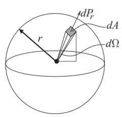
Figure \(\PageIndex{1}\): Free-space spreading loss. The incremental power, \(dP_{r}\), intercepted by the shaded region of incremental area \(dA\) is proportional to \(1/r^{2}\). The solid angle subtended by the shaded area is the incremental solid angle \(d\Omega\). The integral of \(dA\) over the surface of the sphere, i.e. the area of the sphere is \(4πr^{2}\). The total solid angle subtended by the sphere is the integral of \(d\Omega\) over the sphere and is \(4π\) steradians (or \(4π\text{ sr}\)).
characteristic impedance of the originating transmission line to free space. The final aperture is at least one-half wavelength across so that the fields can curl on themselves (i.e., loop back on themselves) and are self-supporting as they leave the antenna.