
4.10: Multipaths and Delay Spread
- Page ID
- 41212

Multipath was discussed previously in Sections 4.6.1 and 4.6.3 in the context of reduction in signal amplitude due to the destructive interference of a signal traveling on several paths. Another effect of multipath is that instances of a signal traveling from a transmitter to a receiver on different paths will arrive at a receiver with various delays. These delays can differ by tens or thousands of nanoseconds which is much longer than the period of a microwave signal, e.g. a \(1\text{ GHz}\) signal has a period of \(1\text{ ns}\).
4.7.1 Delay Spread
Each of the paths supports what is called a signal instance. For a single-tone signal the effect of various delays is for the signal instances to arrive at the receiver with very different phases. As well, the signal instances invariably have different amplitudes resulting in a composite received signal that is an unpredictable combination of constructive and destructive interference. Sometimes the constructive interference will result in a stronger composite received signal but this is not that important. What is much more significant is the destructive interference which will result in signal fades with the signal received being very small at times. Consider two signal instances \(y_{1}(t)\) and \(y_{2}(t)\), traveling from a transmitter to a receiver on paths \(1\) and \(2\) respectively. If \(y_{1}(t)\) and \(y_{2}(t)\) have the same amplitude and phase then the combined signal will only be increased by \(6\text{ dB}\) over a signal that travels on just one path. However if \(y_{1}(t)\) and \(y_{2}(t)\) have the same amplitude but phases that differ by \(180^{\circ}\) then there will be total cancelation and no composite signal will be received. So destructive interference is much more significant than constructive interference.
For cellular radio, in a rural area there can be two or three significant paths, usually taken as paths having signal instances that are within \(20\text{ dB}\) of the largest signal instance. In an urban environment there can be tens of significant paths because there are many reflections from buildings and often there is not an LOS path which would otherwise have the largest signal instance. With multiple paths it is unlikely that there will be total cancelation of the received signal but it is very likely that the received signal will be smaller than if there was one path.
Early cellular radio had narrow bandwidths, e.g. \(200\text{ kHz}\) for 2G’s GSM cellular system, and low-order modulation, e.g. \(2\) bits per symbol and it was sufficient to use the phase-based concepts of constructive and destructive interference to understand the effects of multipath. As channel bandwidths increased and the order of modulation increased it was necessary to consider the actual physical effect of the paths having different delays.
If there is an LOS path, say with no building in the way, then the LOS signal instance will be stronger than a signal instance that travels on any other path. It will also have the smallest delay. This is partly because each non-LOS (NLOS) path will travel further and hence spread out more, and also because there will be signal loss at reflections. If there is scattering or diffraction on a path the amplitude of this signal instance on that path will be even smaller. Even if there is an LOS path, if there are multiple NLOS paths then the combined NLOS signal instances could indeed be larger than the LOS signal instance. If there is not an LOS path then one of the NLOS paths will become
| Frequency \((\text{GHz})\) | Tx-Rx distance \((\text{km})\) | Environment | max. excess delay \(\tau_{d,\text{ max}}\text{ (ns)}\) | median excess delay \(\tau_{d,\text{ med}}\text{ (ns)}\) | |
|---|---|---|---|---|---|
| \(0.43\) | \(3.8^{†}\) | urban | \(1300\) | \(900\) | [18] |
| \(0.90\) | \(2.2\) | rural | \(800\) | \(–\) | [19] |
| \(0.90\) | \(5\) | rural | \(1900\) | \(–\) | [20] |
| \(0.90\) | \(2\) | suburban | \(3700\) | \(300\) | [21] |
| \(0.90\) | \(2.2\) | suburban | \(900\) | \(300\) | [19] |
| \(0.90\) | \(0.6\) | urban | \(700\) | \(200\) | [22] |
| \(0.90\) | \(3.5\) | urban | \(5000\) | \(1100\) | [23] |
| \(0.90\) | \(7.0\) | urban | \(15000\) | \(1900\) | [24] |
| \(0.90\) | \(1.0\) | urban | \(2000\) | \(700\) | [21] |
| \(0.90\) | \(13\) | mountain\(^{$}\) | \(3800\) | \(–\) | [25] |
| \(0.90\) | \(6.0\) | mountain\(^{$}\) | \(1800\) | \(–\) | [26] |
| \(1.35\) | \(3.8^{†}\) | urban | \(1400\) | \(850\) | [18] |
| \(2.26\) | \(3.8^{†}\) | urban | \(1400\) | \(800\) | [18] |
| \(5.75\) | \(3.8^{†}\) | urban | \(1000\) | \(300\) | [18] |
| \(28\) | \(0.052\) | urban LOS | \(754\) | \(<200\) | [27] |
| \(28\) | \(0.097\) | urban NLOS | \(1388\) | \(200\) | [27] |
| \(38\) | \(0.2^{†}\) | urban LOS | \(12\) | \(1.5\) | [28] |
| \(38\) | \(0.2^{†}\) | urban NLOS | \(133\) | \(14\) | [28] |
Table \(\PageIndex{1}\): Measured excess delays for various carrier frequencies, Tx-Rx distances and multipath environments. Data has been normalized where needed so that \(\tau_{d,\text{ max}}\), is the maximum excess delay that is exceeded only \(1\%\) of the time. \(†d\) ranges from \(0.04\text{ km}\) to \(3.8\text{ km}\) and here \(\tau_{d,\text{ max}}\) is the maximum delay exceeded only \(10\%\) of the time. \(‡\) high gain steerable antennas. \($\) urban area surrounded by mountains
the largest received signal instance and it may not have the shortest delay. Generally only signal instances that are within \(20\text{ dB}\) of the largest signal instance must be considered and then the delay, also referred to as ‘delay (\(20\text{ dB}\))’, that matters is the excess delay, \(\tau_{d}\), which is the difference between the earliest and latest arriving signal instances within that \(20\text{ dB}\) window. It is essential that a communications link be maintained a certain percentage of the time, e.g. \(99\%\), for a specified level of service. This minimizes the number of times packets must be re-transmitted and assures acceptable operation of a system. Thus the maximum excess delay, \(\tau_{d,\text{ max}}\) becomes an important metric and determines the interval for which the received signal is not valid, the required guard band to prevent signals from an earlier symbol interval overlapping with the current symbol interval, and also the maximum useful bandwidth of a signal.
It is found that the delay spread increases with distance between the transmitter and receiver, the Tx-RX distance, increases with frequency, and increases with a richer multipath environment. For example, a rural area has few paths but large cell sizes are used and the Tx-Rx distance is relatively large resulting in a large excess delay but a dense urban area has small cells but a rich multipath environment with many reflections from buildings. Measured excess delays for various situations are given in Table \(\PageIndex{1}\). There is a lot of variation in excess delays but it is clearly reduced with smaller cells and a less rich multipath environment.
It is also found that as a mobile unit moves the excess delay and the number of significant paths varies tens or hundreds of times per second depending on the environment but also the mobility, e.g. pedestrian versus highway speeds. However over a millisecond the propagation is found to be effectively fixed and consequently systems are designed with data sent in packets that are usually no longer than a millisecond.
Examining Table \(\PageIndex{1}\) further it is observed that the 2G and 3G cellular bands are below \(2\text{ GHz}\) and the delay spreads can be several milliseconds and even larger with larger Tx-Rx distances in an urban area. At the higher microwave frequencies up to \(6\text{ GHz}\) covering the operating frequency range of 4G, the delay spread is smaller.
The \(28\text{ GHz}\) and \(38\text{ GHz}\) bands are where 5G operates with short Tx-Rx distances. Here the number of paths above \(20\text{ dB}\) is around \(4\) to \(8\) for Tx-Rx separations of \(35\) to \(193\text{ m}\) [27, 28].
The spreads are relatively low and this is largely a result of using high gain steerable antennas which are essential to 5G operation. The high gain antennas reduce the spread of multipath path lengths, and hence reduce the excess delay spread, concentrating the reflected paths close to the transmit and receive antennas.
The prior discussions on multipath effects and the RF link consider a single frequency tone propagating from a transmit antenna and a receive antenna. When a single-tone signal travels on multiple paths there will be destructive and/or constructive interference.
4.7.2 Intersymbol Interference
Intersymbol interference (ISI) occurs when a symbol traveling on one path interferes with the symbol traveling on another path. This is the result of the paths having different delays. The effect of excess delay on the received composite signal is indicated in Figure \(\PageIndex{1}\). Consider the situation where there are four paths with the excess delay of path \(1\) being \(0\) by definition, i.e. \(\tau_{d, 1} = 0\), the excess delay of path \(2\), \(\tau_{d, 2} = 100\text{ ns}\), and so on, \(\tau_{d, 3} = 200\text{ ns}\), and \(\tau_{d, 4} = 300\text{ ns}\). The 2G–5G cellular systems transmit a series of symbols, here \(\mathsf{A, B, C, D,}\) and \(\mathsf{E}\), which have a symbol duration which differs by standard. In Figure \(\PageIndex{1}\) four paths are considered and the four signal instances each travel on a different path and are combined in the receiver’s antenna to yield a composite received signal. The symbols of each of the signal instances overlap causing ISI.
With the 2G GSM system symbol lengths are \(3690\text{ ns}\) and the first \(300\text{ ns}\) of a symbol instance traveling on the first path to arrive has interference from the previous symbol traveling on the other three paths, see Figure \(\PageIndex{1}\)(a). In this case the first \(300\text{ ns}\) of the \(3690\text{ ns}\) of the symbol is garbled. In this example the delay spread is just \(300\text{ ns}\) but this is conservative. Table \(\PageIndex{1}\) indicates that in some environments that the excess delay spread \(1\%\) of the time can be as long as the symbol interval for 2G/GSM (operating below \(2\text{ GHz}\)). So even if the signal strength is high reception may not be possible because of ISI.
With 3G the packet length is \(260\text{ ns}\) so with an excess delay spread of \(300\text{ ns}\) for the four path example the symbol interference is severe, see Figure \(\PageIndex{1}\)(b), and as noted \(300\text{ ns}\) is a very conservative estimate of the excess delay spread. One of the features of 3G is a method for separating out the individual signal instances. Only when there are a very large number of significant paths does 3G have problems. In an urban area sometimes a communication link cannot be established with 2G and 3G even though the signal strength is high.
The 4G system minimizes the problem of ISI by having a very long symbol interval of \(71.35\:mu\text{s}\) and a \(300\text{ ns}\) excess delay spread is a small fraction of the symbol length. The symbol interval is considerably longer than any of the maximum delay spreads given in Table \(\PageIndex{1}\). Also the 4G standard
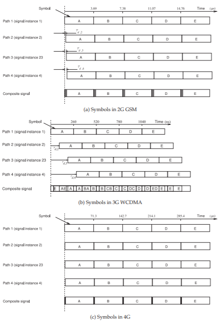
Figure \(\PageIndex{1}\): The effect of excess delay on symbol interference when there are four paths. The excess delay of each path, \(\tau_{d, x}\), increases by \(100\text{ ns}\). Five symbols are shown: \(\mathsf{A, B, C, D}\), and \(\mathsf{E}\). The 2G GSM standard has a symbol duration of \(3.6928\:\mu\text{s}\), the 3G WCDMA standard has a symbol duration of \(260\text{ ns}\), and the 4G OFDM standard has a symbol duration of \(71.35\:\mu\text{s}\). The situation with 5G is similar to that for 4G.
has a guard time band known as a cyclic prefix. (The cyclic prefix is a bit more than a guard band as it involves repeating the end of symbol but this extra feature will be discussed latter.) The cyclic prefix can be either \(4.7\:\mu\text{s},\: 5.2\:\mu\text{s},\: 16.7\:\mu\text{s}\), or \(33.3\:\mu\text{s}\) accommodating various excess delay spreads. This is more than enough to avoid the problem of ISI as any of the maximum excess delays listed in Table \(\PageIndex{1}\) are less than the maximum cyclic prefix length. The long symbol interval implies a very narrow bandwidth or subchannel bandwidth. A 4G system communicates with a user using a very large number of sub-channels thus supporting high data rates.
4.7.3 Summary
Various excess delays on different paths causes intersymbol interference. High levels of intersymbol interference results in the failure to establish a communication link. Excess delay is a fundamental limitation with the 2G/GSM system and the only solution is to use very small cells in urban environments which have many significant signal paths. The 3G system employs a coding technique that enables the first few different paths to be resolved thus limiting the problem of ISI but not eliminating it. The 4G system, and 5G operates similarly, employs a long guard time, the cyclic prefix, to avoid ISI completely.