
4.12: Antenna Array
- Page ID
- 41214

An antenna array comprises multiple radiating elements, i.e. individual antennas, and focuses a transmit beam in a desired direction. In Figure \(\PageIndex{2}\) the field pattern in the plane of the earth produced by an array of \(30\) antenna elements arranged horizontally is shown. The fields from each
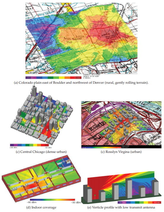
Figure \(\PageIndex{1}\): Radio coverage profiles with \(900\text{ MHz}\) transmitter except for (d) which is for \(2.45\text{ GHz}\). Calculated using Wireless Insite\(^{®}\). Copyright Remcom, Inc. Used with permission.
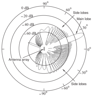
Figure \(\PageIndex{2}\): Electric field pattern from a \(30\) element array of antennas spaced \(0.65\lambda\) apart. The sidelobe levels are about \(40\text{ dB}\) below the power level of the main lobe. The same signal is presented to the antenna elements except that phases of the signal at each antennas is adjusted to produce a main beam directed at \(20\) degrees. The signals to each antenna are thus correlated. After [29].
antenna element combined to narrow and strengthen the main beam. Side (or grating) lobes are produced and these will result in some interference but their level here is \(40\text{ dB}\) below that of the main beam. This is another way of managing interference in a cellular system but the direction to the mobile unit must be known. Antenna arrays are used in 5G. The affect of the array is to increase the power density of the main beam and the density relative to that of an isotropic antenna is called the directional gain of the array, \(D_{\text{Array}}\), and is the product of the antenna gain, \(G_{A}\), of an individual antenna element and the array gain, \(G_{\text{Array}}\):
\[\label{eq:1}D_{\text{Array}}=G_{\text{Array}}G_{A} \]
The maximum value of \(G_{\text{Array}}\) is \(N\) for an \(N\) element array. So the maximum directional gain of the array in \(\text{dBi}\) is
\[\label{eq:2}D_{\text{Array}}|_{\text{dBi}}=G_{A}|_{\text{dBi}}+10\log N \]