
5.6: Processing Gain
- Page ID
- 41220

In digital radio the demodulated signal is a binary signal that includes information bits, coding bits, as well as bits that are in error which contributes to a raw bit error rate (BER). In the receiver decoding creates a smaller bitstream with just the information bits and which has a relatively low BER. Another way of looking at what happens is that the signal-to-interference ratio (SIR) of the decoded signal divided by the SIR of the raw signal represents a gain and this gain is called the processing gain. In 2G cellular radio this processing gain is also called the coding gain. With 3G spreading codes are used in addition to error correction codes with both reducing the bit error rate but now the gain from despreading is called spreading gain and the gain from error correction coding is called coding gain. The processing gain is now the product of spreading gain and coding gain. With 4G and 5G the functions of the spreading codes and error correction codes merge so just the term processing gain is used.
5.6.1 Energy of a Bit
Processing gain (\(G_{P}\)) occurs when demodulating and recovering an information bitstream and is the ratio of the SIR of the processed signal to the SIR of the unprocessed signal so \(G_{P}\) captures the amount that the SIR increases. \(G_{P}\) is a measure of the additional noise immunity obtained
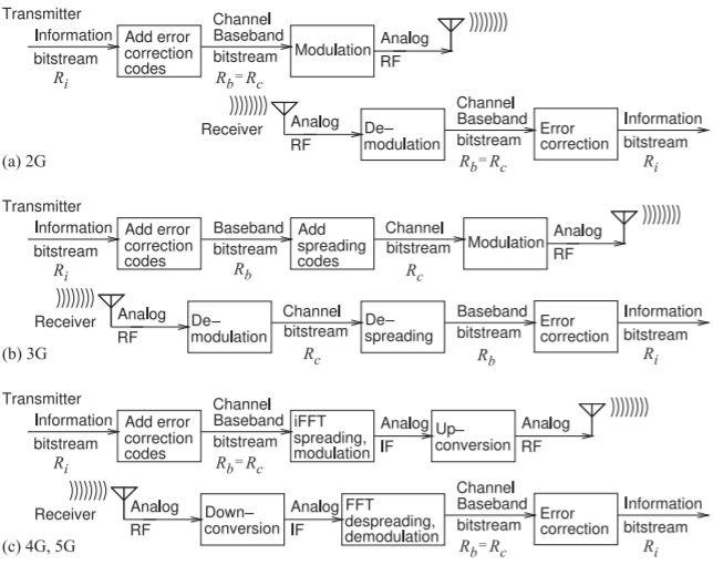
Figure \(\PageIndex{1}\): Flow of information in digital cellular radio with \(R_{i},\: R_{b},\) and \(R_{c}\) being the information, baseband, and channel bit rates, respectively.
through decoding and demodulation. There are various formulas for \(G_{P}\) depending on whether the processed signal is the baseband bitstream with or without error correction coding, and whether the unprocessed signal is the analog RF signal, the channel bitstream, or the channel symbol (i.e. chip) stream. Processing gain is an essential concept in cellular radio and really is what makes it work. In the following, reference will be made to three bitstreams in the transmitter which will be recovered in the receiver. The first is the information bitstream with a bit rate \(R_{i}\) (in units of \(\text{bit/s}\)). To this error correction coding can be used to produce a baseband bitstream with baseband bit rate \(R_{b} > R_{i}\). In some generations of radio the baseband bitstream is modulated on a carrier and the baseband bitstream is the same as the channel bitstream. The bitstreams are shown in the depiction in Figure \(\PageIndex{1}\)(a) of the information flow in 2G cellular radio.
In 3G cellular radio relatively fast spreading codes merged with the baseband bitstream to produce a much faster channel bitstream with bit rate \(R_{c} ≫ R_{b}\). The introduction of this separate third bitstream is the depiction in Figure \(\PageIndex{1}\)(b) of the information flow in 3G cellular radio. The third bitstream is the channel bitstream with bit rate \(R_{c}\) and this is the bitstream that is modulated to produce a modulated signal with a constellation diagram where each symbol representing \(b\text{ bits}\).
In 4G and 5G cellular radio error correction codes are merged with the information bitstream to produce a baseband bitstream and this is spread during a first stage of the modulation process which produces an analog intermediate frequency modulated signal. Details of this process will be given later. There is not a separate spreading code so that the baseband and channel bitstreams are the same and \(R_{c} = R_{b}\).
Derivation of the coding, spreading, and processing gains is based on the energy of a bit and the energy of the noise in the interval corresponding to a bit. The energy of a bit in the \(x\)th bitstream (\(x = i,\: b,\: c\) for information, baseband, and channel respectively) is denoted \(E_{b, x}\) and the energy of the noise corresponding to the duration of the bit is denoted \(N_{o, x}\). The digital equivalent of the analog SIR is \(E_{b}/N_{o}\) (pronounced E-B-N-O for EBNO) and the effective SIR of the \(x\)th bitstream is
\[\label{eq:1}\text{SIR}_{\text{eff, }x}=\frac{E_{b, x}}{N_{o, x}} \]
A bitstream of course is a binary signal and the noise in the bitstream is manifested as binary errors in the bitstream. Consider a sequence of \(7\text{ bits}\), ideally \(\mathsf{1001110}\), with one of the bits being in error so that the bitstream recovered is \(\mathsf{1001010}\) where \(1\text{ bit}\) in \(7\) is in error so \(\text{SIR}_{\text{eff}} = 7\).
5.6.2 Coding Gain
There are many types of error correction coding schemes with some schemes better for certain types of errors\(^{1}\). Generalizing, with each extra error correcting bit added to an information bitstream to produce the baseband bitstream, one error in the recovered bitstream can be corrected. Thus the processing gain due to coding (and often called just coding gain) in going from the baseband to the information bitstream is
\[\label{eq:2}G_{PC}=\frac{\text{SIR}_{\text{eff, }i}}{\text{SIR}_{\text{eff, }b}}=\frac{E_{b, i}/N_{o, i}}{E_{b, b}/N_{o, b}}=\frac{R_{b}}{R_{i}} \]
This is a bit-wise processing gain as it applies to bitstreams. The coding gain here is not restricted to error correction coding as there are other types of codes called spreading codes that have a similar property of providing redundancy that can be used to remove errors. Not codes are \(100\%\) effective. However Equation \(\eqref{eq:2}\) is the best simple measure of processing gain when only bitstreams are considered. It provides the coding gain of one bitstream derived from a second bitstream to which coding has been used to randomize and increase the rate of a bitstream and thus introduce redundancy.
5.6.3 Spreading Gain
Equation \(\eqref{eq:2}\) can be rearranged so that the information EBNO is
\[\label{eq:3}\frac{E_{b, i}}{N_{o, i}}=G_{PC}\frac{E_{b, b}}{N_{o, b}} \]
The processing gain determined in Equation \(\eqref{eq:2}\) applies to bitstreams and does not include the effect of modulation. A second form of the processing gain relates the SIR of the analog RF signal, i.e. \(\text{SIR}_{\text{RF}}\), to the EBNO of the baseband bitstream. To include the effect of modulation it is recognized that what is modulated and transmitted are symbols and the transitions from one symbol to another. The energy of a symbol is denoted \(E_{s}\) and this energy is shared by the \(b\text{ bits}\) associated with the symbol. Thus a channel bit will have the energy \(E_{b, c} = E_{s}/b\). In digital radio power levels of transmitted signals are adjusted so that at most one received channel bit can be in error per received symbol. Thus if received noise results in a symbol error it will affect just one bit. That is, the symbol noise will be the same as the bit noise, \(N_{o, c} = N_{o}\) where \(N_{o}\) is the noise energy in the duration of one symbol. Thus the effective SIR of the channel bitstream is
\[\label{eq:4}\text{SIR}_{\text{eff, }c}=\frac{E_{b, c}}{N_{o, c}}=\frac{E_{b, c}}{N_{o}}=\frac{E_{s}/b}{N_{o}} \]
Development is completed by relating the energy of a symbol to the RF signal energy. For PSK modulation all of the symbols have the same energy. (The energy of each symbol is not the same for modulation formats such as QAM where symbols have different energy levels and a more sophisticated derivation is required than that provided here.) Also the noise energy in the duration of a symbol is the same for all symbols for all modulation formats. Thus the effective SIR of a symbol is
\[\label{eq:5}\text{SIR}_{\text{RF}}=\frac{E_{s}}{N_{o}} \]
Thus the effective SIR of the channel bitstream is (combining Equations \(\eqref{eq:4}\) and \(\eqref{eq:5}\),
\[\label{eq:6}\text{SIR}_{\text{eff, }c}=\frac{E_{b, c}}{N_{o, c}}=\frac{1}{b}\text{SIR}_{\text{RF}} \]
The processing gain relating the EBNO of the recovered baseband bitstream to the SIR of the RF signal can be defined as the processing gain due to spreading and modulation and this is sometimes called just the spreading gain \(G_{PS}\). It is defined here as the ratio of the effective SIR of the baseband bitstream and the RF SIR (and using Equation \(\eqref{eq:6}\)):
\[\label{eq:7}G_{PS}=\frac{E_{b, b}/N_{o, b}}{\text{SIR}_{\text{RF}}}=\frac{1}{b}\frac{E_{b, b}/N_{o, b}}{\text{SIR}_{\text{eff, }c}}=\frac{1}{b}\frac{\text{SIR}_{\text{eff, }b}}{\text{SIR}_{\text{eff, }c}} \]
This can be rearranged so that the EBNO of the baseband bitstream is
\[\label{eq:8}\frac{E_{b, b}}{N_{o, b}}=G_{PS}\text{SIR}_{\text{RF}} \]
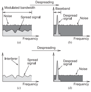
Figure \(\PageIndex{2}\): Increase in SNR obtained by despreading a spread-spectrum signal: (a) the spectrum of noise and a spread-spectrum signal that has a power below the level of the noise; (b) the despread signal, where the power distribution of the noise is not changed but the despread signal is confined to a narrower bandwidth called the baseband bandwith; (c) a signal with a single-tone interferer; and (d) after despreading where the power of the interferer spread across the the original bandwidth.
Equation \(\eqref{eq:7}\) includes the ratio of the effective SIRs of two bitstreams and this was related to the bit rates of the bitstreams in Equation \(\eqref{eq:2}\) where the faster bitstream is coded (or spread) to enable recovery from errors. Using the result in Equation \(\eqref{eq:2}\), Equation \(\eqref{eq:7}\) can be written as
\[\label{eq:9}G_{PS}=\frac{1}{b}\frac{\text{SIR}_{\text{eff, }b}}{\text{SIR}_{\text{eff, }c}}=\frac{1}{b}\frac{R_{c}}{R_{b}} \]
Using this the EBNO of the baseband bitstream is
\[\label{eq:10}\frac{E_{b, b}}{N_{o, b}}=\text{SIR}_{\text{eff, }b}=\frac{1}{b}\frac{R_{c}}{R_{b}}\text{SIR}_{\text{RF}}=\frac{1}{b}G_{PC}\text{SIR}_{\text{RF}} \]
Then the EBNO of the information bitstream is
\[\label{eq:11}\frac{E_{b, i}}{N_{o, i}}=G_{PC}\frac{E_{b, b}}{N_{o, b}}=G_{PC}G_{PS}\text{SIR}_{\text{RF}}=G_{P}\text{SIR}_{\text{RF}}=\frac{1}{b}\frac{R_{c}}{R_{i}}\text{SIR}_{\text{RF}} \]
where the processing gain
\[\label{eq:12}G_{P}=G_{PC}G_{PS} \]
5.6.4 Spreading Gain in Terms of Bandwidth
The spreading gain that results from spreading a baseband bitstream in a transmitter and then despreading in a receiver is illustrated graphically in Figure \(\PageIndex{2}\). The modulated signal shown in Figure \(\PageIndex{2}\)(a) is the “spread signal” which here has a power density which is below that of the noise. Following despreading all of the energy in the modulated RF signal is correlated with the spreading code (it was spread using the spreading code) and is collapsed to the despread signal shown in Figure \(\PageIndex{2}\)(b). Only the signal correlated to the despreading code is collapsed to the smaller baseband bandwidth. Noise is rearranged with the spectral density of the noise unchanged so that the total noise energy in the baseband for the duration of a bit of data, i.e. the noise in the baseband bandwidth \(B_{b}\), is greatly reduced by the ratio of the modulated bandwidth to the baseband bandwidth.
In Equation \(\eqref{eq:9}\) \(R_{c}\) is related to the bandwidth Bm of the modulated carrier by the modulation efficiency as \(\eta_{c} = R_{c}/B_{m}\)(see Equation (5.5.3)). Also the minimum bandwidth of a baseband bitstream with a bit rate \(R_{b}\) is the baseband bandwidth \(B_{b} = R_{c}\). So Equation \(\eqref{eq:9}\) becomes
\[\label{eq:13}G_{PS}=\frac{\eta_{c}}{b}\frac{B_{m}}{B_{b}} \]
Ideally for a modulation scheme \(\eta_{c} = b\) so that
\[\label{eq:14}G_{PS,\text{ ideal}}=\frac{B_{m}}{B_{b}} \]
For all modulation schemes other than BPSK where \(\eta_{c}\) can be very close to \(b\), the spreading gain will be less than \(G_{PS,\text{ ideal}}\) as in reality \(\eta_{c} < b\), see Table \(\PageIndex{1}\). If both spreading and error correction coding are used the two processing gains in Equations \(\eqref{eq:2}\) and \(\eqref{eq:13}\) can be multiplied.
5.6.5 Symbol Error Rate and Bit Error Rate
With digital modulation, symbols (i.e., groups of bits) are transmitted rather than individual bits. As the modulation order increases, the number of symbols increases and there is a smaller margin between the symbols. That is, on a constellation diagram there are more symbols and the symbols are closer together. For the same signal and noise levels, as the modulation order increases the probability of a symbol error will increase and thus the symbol error rate (SER) increases. However the bit error rate (BER) increases more slowly than the SER. This is because if the SIR is high enough, the only possible errors will be nearest-neighbor errors (on a constellation diagram). If there are at least \(b\text{ bits}\) per symbol the BER will be less than the symbol error rate by a factor of \(b\) as errors are at most one bit per symbol since the modulation order or the signal power level are adjusted to ensure this. If it is not possible to achieve a maximum of one bit error per symbol error then communication is lost. The rest of this section treats this analysis more mathematically.
The discussion begins with the SIR of the incoming RF signal. Through sampling of the RF signal at appropriate times (determined by the recovered carrier) discrete symbols are obtained. The digital form of SIR relates the energy of a symbol, \(E_{s}\), to the noise and interference energy corresponding to the symbol (the noise and interference in the duration of the symbol). The height of the double-sided noise spectral density is conventionally taken as \(N_{o}/2\), so the noise power corresponding to a symbol is \(N_{o}\). Thus [16, 17, 18]
\[\label{eq:15}\frac{E_{s}}{N_{o}}=\text{SIR} \]
Error in a digitally modulated communications system is first manifested as a symbol error that occurs when a symbol selected in a receiver is not the symbol transmitted. The probability of a symbol error is a function of \(E_{s}/N_{o}\). However it is not always possible to develop a closed-form expression relating the two. For a BPSK system it can be derived. The probability of
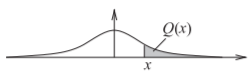
Figure \(\PageIndex{3}\): Gaussian distribution function showing the \(Q\) function as the area of the shaded region.
a symbol error, the SER, is [16, p. 187]
\[\label{eq:16}\text{SER}_{\text{BPSK}}=\text{Pr}[\text{symbol error}]=\text{Pr}_{s}^{\text{BPSK}}=Q\left(\sqrt{\frac{2E_{s}}{N_{o}}}\right)=Q\left(\sqrt{2\cdot\text{SIR}}\right) \]
where \(Q(x)\) is known as the \(Q\) function [16] and is the integral of the tail of the Gaussian density function (see Figure \(\PageIndex{3}\)). It can be expressed in terms of the error function \(\text{erf}(x)\) and complementary function \(\text{erfc}(x)\) [16, page 63]:
\[\label{eq:17}Q(x)=\frac{1}{2}\text{erfc}\left(\frac{x}{\sqrt{2}}\right)=\frac{1}{2}\left[1-\text{erf}\left(\frac{x}{\sqrt{2}}\right)\right] \]
For \(M\text{-PSK}\) [16, page 191] the SER is
\[\label{eq:18}\text{SER}_{M\text{-PSK}}=\text{Pr}_{s}^{M\text{-PSK}}\approx 2Q\left[\sqrt{\frac{2E_{s}}{N_{o}}}\sin\left(\frac{\pi}{M}\right)\right] \]
where \(M\) is the number of symbols (e.g. for 8-QPSK \(M = 8\)). To see the effect of higher-order modulation (i.e., higher \(M\)) consider Equation \(\eqref{eq:18}\). As the order of modulation increases, \(M\) increases, and the argument of \(Q\) reduces, thus increasing SER.
The per-bit SIR is obtained after noting that each symbol can represent several bits. With a uniform constellation and the same number of bits per symbol, \(b\), the signal energy received per bit is
\[\label{eq:19}E_{b}=E_{s}/b,\qquad b=\log_{2}M \]
and
\[\label{eq:20}M=2^{b} \]
For high SIR, a symbol error is the erroneous selection of a nearest neighbor symbol by the receiver. So with Gray code mapping (also called Gray mapping), such a symbol error results in only a single bit being in error. Thus the probability of a bit error, the BER, is
\[\label{eq:21}\text{Pr}[\text{bit error}]=\text{Pr}_{b}=\frac{1}{b}\text{Pr}_{s} \]
The final results are the bit error probabilities for BPSK and M-PSK [16, page 193]:
\[\begin{align}\label{eq:22}\text{BER}|_{\text{BPSK}}&=\text{Pr}_{b\text{, BPSK}}=Q\left(\sqrt{2E_{s}/N_{o}}\right) =Q\left(\sqrt{2\cdot\text{SIR}}\right) \\ \text{BER}|_{M\text{-PSK}}&=\text{Pr}_{b,M\text{-PSK}}=\frac{2}{b}Q\left[\sqrt{2E_{s}/N_{o}}\sin\left(\frac{\pi}{M}\right)\right] \\ \label{eq:23} &=\frac{2}{b}Q\left[\sqrt{2\cdot\text{SIR}}\sin\left(\frac{\pi}{M}\right)\right]\end{align} \]
Thus for the same SIR the probability of bit errors, the BER, grows with higher-order modulation (i.e., larger \(M\)), but not as fast as SER. At the same time the number of bits transmitted increases. These extra bits are use to embed error correction codes. The net gain in throughput can be tremendous as long as the SIR is high enough.
Example \(\PageIndex{1}\): Symbol Error Rate
Calculate the SER and BER for QPSK and 8-PSK if the SIR is \(10\text{ dB}\).
Solution
SER is found by evaluating Equation \(\eqref{eq:18}\). For \(\text{SIR} = 10\text{ dB},\: E_{s}/N_{o}= 10^{(\text{SIR}_{\text{dB}}/10)} = 10\). For QPSK, \(M = 4\) and \(b = 2\), and the SER is
\[\begin{align}\text{SER}_{\text{QPSK}}&=\text{Pr}_{s}^{M\text{-PSK}}\approx 2Q\left(\sqrt{\frac{2E_{s}}{N_{o}}}\sin\left(\frac{\pi}{M}\right)\right)=2Q\left[\sqrt{20}\sin\left(\frac{\pi}{4}\right)\right] \nonumber \\ \label{eq:24} &=2Q(3.162)=\left[1-\text{erf}(3.162/\sqrt{2})\right]=0.001565\end{align} \]
For 8-PSK, \(M = 8\) and \(b = 3\), and the SER is
\[\begin{align}\text{SER}_{8\text{-PSK}}&=\text{Pr}_{s}^{M\text{-PSK}}\approx 2Q\left[\sqrt{\frac{2E_{s}}{N_{o}}}\sin\left(\frac{\pi}{M}\right)\right]=2Q\left(\sqrt{20}\sin\left(\frac{\pi}{8}\right)\right)\nonumber \\ \label{eq:25}&=2Q(1.711)=0.08701\end{align} \]
The corresponding BERs are
\[\label{eq:26}\text{BER}_{\text{QPSK}}=\frac{1}{2}\text{SER}_{\text{QPSK}}=0.000783\quad\text{and}\quad\text{BER}_{8\text{-PSK}}=\frac{1}{3}\text{SER}_{8\text{-PSK}}=0.0290 \]
5.6.6 Summary
The formulas for processing gain developed above are only approximate as many simplifications were made. One assumption is that the error correction coding is fully randomized bits but in practice there are many error correction codes that address particular types of errors. The aim of error correction coding is to recover from errors not necessarily to achieve processing gain.
Another caveat to the processing gain formulas developed here is that it considered the energy of a symbol as being the same for all symbols. While this is true for PSK modulation it is not true for all modulation formats. Considerable effort is put into developing better estimates that capture the essence of processing gain but in a more rigorous manner. Still the simple formulas provide the required insight into the effect of using error correction and spreading codes.
In 2G cellular radio processing gain is achieved using error correction codes alone and a separate spreading code is not used. Thus in 2G the baseband bits are also the channel bits used directly in modulating the RF carrier. The extra bits provide redundancy and the ability to recover from some errors resulting from noise. In 3G spreading codes as well as error correcting codes are used. A spreading code greatly increases the bit rate of the channel bitstream above that of the baseband bitstream and the bandwidth of the modulated carrier is much greater than that needed to transmit the baseband bitstream. Generally error correcting codes do not increase the bit rate by more than a factor of \(2\). Thus in 3G the processing gain achieved with the error correction codes is almost insignificant compared to
| Description | Definition | Formula | Equation |
|---|---|---|---|
| Coding gain, processing gain from error correction coding. Calculated for bitstreams. | \(G_{PC}=\frac{E_{b, i}/N_{o, i}}{E_{b, b}/N_{o, b}}\) | \(G_{PC}=\frac{R_{b}}{R_{i}}\) | \(\eqref{eq:2}\) |
| Processing gain from spreading calculated on a bitstream basis | \(G_{PS}=\frac{E_{b, c}/N_{o, c}}{E_{b, b}/N_{o, b}}\) | \(G_{PS}=\frac{1}{b}\frac{R_{c}}{R_{b}}\) | \(\eqref{eq:9}\) |
| Processing gain from spreading in terms of bandwidth. | \(G_{PS}=\frac{E_{b, b}/N_{o, b}}{\text{SIR}_{\text{RF}}}\) | \(G_{PS}=\frac{\eta_{c}}{b}\frac{B_{m}}{B_{b}}\) | \(\eqref{eq:13}\) |
| Processing gain | \(G_{P}=\frac{E_{b, c}/N_{o, c}}{E_{b, i}/N_{o, i}}\) | \(G_{P}=G_{PC}G_{PS}\) | \(\eqref{eq:12}\) |
| EBNO | \(E_{b, i}/N_{b, i}\) | \(E_{b, i}/N_{b, i}=G_{P}\text{SIR}_{\text{RF}}\) | \(\eqref{eq:8}\) |
Table \(\PageIndex{1}\): Processing gain definitions. \(R_{i}\) is the information bit rate, \(R_{b} > R_{i}\) is the baseband bit rate after error correction coding of the information bitstream, and \(R_{c} > R_{b}\) is the channel bit rate after spreading the baseband bitstream. Reference is made to the \(x\)th bitstream with \(x = i, b,\) or \(c\) indicating the information, baseband, or channel bitstreams respectively. \(B_{b, x}\) is the energy of a bit in the \(x\)th bitstream, and \(N_{o, x}\) is equivalent noise energy corresponding to a bit in the \(x\)th bitstream. \(E_{s}\) is the energy of a symbol with \(b\text{ bits}\) per symbol. \(B_{m}\) is the bandwidth of the modulated carrier and \(B_{b}\) is the bandwidth of the baseband signal.
that obtained from spreading the signal.
In 4G and 5G error correction coding also provides spreading and there is not a separate spreading code. The 4G and 5G systems have great complexity.
A summary of the key results for processing gain is given in in Table \(\PageIndex{1}\).
Example \(\PageIndex{2}\): Processing Gain
A new communication system is being investigated for sending data to a printer. The system will use GMSK modulation and a channel with \(10\text{ MHz}\) bandwidth and the baseband bit rate will be \(1\text{ Mbit/s}\). The modulation format will result in a spectrum that distributes (i.e. spreads) power almost uniformly over the \(10\text{ MHz}\) bandwidth.
- What is the processing gain?
The most efficient way to spread the signal across the \(10\text{ MHz}\) of available bandwidth is to use a combination of error correction and spreading. Referring to Table 2.9.1, GMSK has a modulation efficiency \(\eta_{c}\) of \(1.354\text{ bit/s/Hz}\), so that the channel bit rate \(R_{c} = 13.54\text{ Mbit/s}\). Each symbol in GMSK represents two bits so \(b = 2\). The information bit rate \(R_{i} = 1\text{ Mbit/s}\) and so coding at the rate of \(12.54\text{ Mbit/s}\) will be used and \(R_{b} = (R_{i} + 12.54\text{ Mbit/s}) = 13.54\text{ Mbit/s}\).
There are two processing gains. The coding gain is determined using Equation \(\eqref{eq:2}\):
\[G_{PC}=\frac{R_{b}}{R_{i}}=\frac{13.54\text{ Mbit/s}}{1\text{ Mbit/s}}=13.54=11.31\text{ dB}\nonumber \]
The spreading gain, using Equation \(\eqref{eq:9}\), is
\[G_{PS}=\frac{1}{b}\frac{R_{c}}{R_{b}}=\frac{1}{2}\frac{1\text{ Mbit/s}}{1\text{ Mbit/s}}=0.5=-3\text{ dB}\nonumber \]
Thus the processing gain
\[G_{P}=G_{PC}G_{PS}=6.77=8.31\text{ dB}\nonumber \]
Another way of calculating the spreading gain is to consider the modulated bandwidth, \(B_{m} = 10\text{ MHz}\) and the baseband bandwidth \(B_{b} = 1\text{ MHz}\) (taken to be numerically equal to \(R_{b}\)). The processing gain due to spreading, from Equation \(\eqref{eq:13}\):
\[G_{PS}=\frac{\eta_{c}}{b}\frac{B_{m}}{B_{b}}=\frac{1.354}{2}\frac{10\text{ MHz}}{1\text{ MHz}}=6.770=8.31\text{ dB}\nonumber \] - If the received RF SIR is \(\text{SIR}_{\text{RF}} = 6\text{ dB}\), what is the effective system SIR (or \(E_{b}/N_{o}\)) after the digital signal processor?
\[\text{Effective SIR}=\frac{E_{b, i}}{N_{o, i}}=G_{P}\text{SIR}_{\text{RF}}=8.31\text{ dB}+6\text{ dB}=14.32\text{ dB}\nonumber \]
Example \(\PageIndex{3}\): Signal-to-Interference Ratio
At the output of a receiver antenna, the level of interfering signals is \(1\text{ pW}\), the level of background noise is \(500\text{ fW}\), and the level of the desired signal is \(4\text{ pW}\).
- What is the SIR? Note that SIR includes the effect of the signal, interference, and noise.
- If the processing gain is \(20\text{ dB}\) and 16-QAM is the modulation scheme used, what is the effective system SIR, that is, what is the signal energy in a bit versus the noise energy in the duration of the bit (i.e., \(E_{b}/N_{o}\))?
Solution
- Interfering signal \(P_{I} = 1\text{ pW},\text{ noise signal }P_{N} = 500\text{ fW}\), and signal \(P_{S} = 4\text{ pW}\).
\[\begin{aligned}\text{SIR}_{\text{RF}}&=P_{S}/(P_{I}+P_{N})\nonumber \\ &=4\text{ pW}(1\text{ pW}+0.5\text{ pW})=4/1.5 =2.667=4.26\text{ dB}\nonumber\end{aligned} \nonumber \] - Processing gain \(G_{P} = 20\text{ dB}\) so, from Equation \(\eqref{eq:11}\)
\[\text{Effective SIR}=\frac{E_{b, i}}{N_{o}}=G_{P}\cdot\text{SIR}_{\text{RF}}=20\text{ dB}+4.26\text{ dB}=24.26\text{ dB}\nonumber \]
Footnotes
[1] The error codes used in cellular radio are forward error correction (FEC) codes also called channel codes. There are many FEC codes broadly categorized as either block codes (because they work on blocks of data) or convolution codes (because they work on arbitrary-length bitstreams). The various FEC codes use different models (i.e. assumptions) about the types of errors encountered. The selection of the FEC code to use is a design choice based on the available computing power and the nature of the errors, e.g. random or long strings of errors.