
4.7: Linearization
- Page ID
- 46073
Linearization refers to strategies that compensate for the inherent phase and amplitude nonlinearities of RF amplifiers. There are three basic strategies that introduce a correction mechanism [45, 46, 47, 48, 49, 50]:
- predistortion linearization,
- feed-forward linearization, and
- linearization by design.
Reducing distortion using the above techniques enables an amplifier to operate at higher efficiency while producing the maximum permissible amount of distortion.
4.7.1 Predistortion
The predistortion concept is illustrated in Figure 4.6.11. The essential nonlinearity of an RF amplifier is a tanh-like response, as shown in
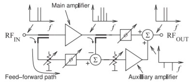
Figure \(\PageIndex{1}\): Feed-forward linearizer concept with the plots showing the spectra in different parts of the circuit.
Figure 4.6.11(a). With predistortion, a compensation network that has a complementary response, such as that shown in Figure 4.6.11(b), is developed [49, 50]. When the compensation network precedes the amplifier, ideally the output is linearized with little final distortion (see Figure 4.6.11(c)). Predistortion can be analog predistortion, as shown here, or the compensating function can be performed at baseband in a DSP unit. Predistortion requires a good behavioral analytic model of the amplifier from which distortion can be calculated. Then this model is reverted to synthesize the compensation network. Variations of the predistortion strategy include adaptive predistortion in which the distortion at the output of the amplifier is regularly sampled during operation and the coefficients of the compensation network updated. The linearization achievable is limited by the accuracy of the reversion synthesis, the stability of the amplifier circuit, and the stability of the adaptive process.
4.7.2 Feed-Forward Linearization
A linearization strategy that does not require characterization of the nonlinear process is feed-forward linearization, the concept of which is shown in Figure \(\PageIndex{1}\) [48]. In Figure \(\PageIndex{1}\) a two-tone input signal is considered for illustration. The two-tone signal is sampled prior to amplification by the main amplifier, which produces intermodulation distortion where third-order intermodulation distortion is shown in the spectrum at the main amplifier output. The original undistorted input signal is sampled by the directional coupler at the input and, following amplitude and phase adjustment, is compared to the sampled distorted signal at the output of the main amplifier. The difference is then the distorted waveform, which is amplified by an auxiliary amplifier and then added into the main signal path (after appropriate phase adjustment). This addition ideally cancels distortion in the high-power signal. Feed-forward linearization requires a very linear auxiliary amplifier, but this is easier to achieve than for the main amplifier since the auxiliary amplifier operates at much lower power levels.
4.7.3 Summary
The third category of linearization is linearization by design, achieved by choosing amplifier topologies that inherently compensate for distortion. Many of these topologies will be considered in the next sections.
The various linearization strategies can be combined, but linear by design topologies are very important, as predistortion and feed-forward linearization can consume significant DC power, especially for wideband signals.