
5.2: Oscillator Theory
- Page ID
- 46085
Microwave oscillators are usually implemented as reflection oscillators with two connected one-port circuits with one being an active device configured as a one-port and presenting a negative conductance, and a second oneport network being the tank or resonator network which must be designed to have specific admittance versus frequency characteristics that ensure stability. However the great body of network theory available derives from control theory and general circuit theory, and is based on a two-port oscillator with linear frequency-selective feedback.
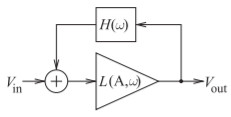
Figure \(\PageIndex{1}\): Representation of a feedback oscillator based on a two-port active device.
5.2.1 Theory of Oscillation
The two-port view of oscillators is based on the amplifier plus feedback loop shown in Figure \(\PageIndex{1}\). Here \(L(A, \omega )\) describes the characteristics of an amplifier whose transfer function is dependent on both amplitude, \(A\), and radian frequency, \(\omega\), and has a magnitude greater than \(1\). \(H(\omega )\) describes the transfer characteristics of a linear feedback network that is dependent only on frequency. The output of the feedback system is described by
\[\label{eq:1}V_{\text{out}}=L(A,\omega )V_{\text{in}}+L(A,\omega )H(\omega )V_{\text{out}} \]
and so
\[\label{eq:2}V_{\text{out}}=\frac{L(A,\omega )V_{\text{in}}}{1-L(A,\omega )H(\omega )} \]
The aim of most oscillator design is to use an active device whose characteristics are independent of frequency but whose transfer response depends on the output amplitude. Then Equation \(\eqref{eq:2}\) becomes
\[\label{eq:3}V_{\text{out}}=\frac{L(A)V_{\text{in}}}{1-L(A)H(\omega )} \]
Oscillation begins with input noise when the oscillator is powered on. If the denominator of Equation \(\eqref{eq:3}\) is close to zero, oscillations build up at a frequency determined by the feedback network. As the amplitude of the oscillations builds, \(L(A)\) compresses until the denominator is finite but close to zero\(^{1}\), and there are stable oscillations. Stable oscillation is no accident and is the result of careful design, and much depends on the nature of the feedback network. When an amplifier becomes unstable, for example, the signal produced is often chaotic, with rapid variations in amplitude and frequency, and is not the single frequency sinusoid required of an oscillator.
5.2.2 Basic Oscillator Configurations
There are two dominant types of feedback networks, the Pi- and T-type networks, shown in Figure \(\PageIndex{2}\). Three Pi-type networks have proven to be particularly suited to the amplitude saturation characteristics of FET and BJT active devices and, ignoring parasitic capacitances, they result in stable oscillation. These are the Hartley, Colpitts, and Clapp circuits shown in Figure \(\PageIndex{3}\). The grounds shown can be considered to be common terminals instead.
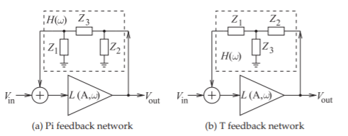
Figure \(\PageIndex{2}\): Feedback oscillator with Pi- and T-type feedback networks.
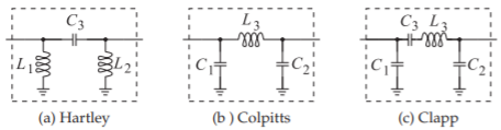
Figure \(\PageIndex{3}\): Basic oscillator feedback networks.
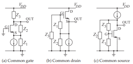
Figure \(\PageIndex{4}\): Circuit schematics for FET feedback oscillators using Pi-type feedback networks. The current sources provide bias.
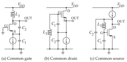
Figure \(\PageIndex{5}\): Circuit schematics for Colpitts FET oscillators. The current sources provide bias. (In (a) \(C_{1}\) is across the input of the gate-source transistor with connection through the ground.)
The Hartley and Colpitt’s basic oscillator configurations have three large energy storage elements. The Clapp oscillator has four significant energy storage elements but it is important because sometimes it is desirable to use a very high \(Q\) resonator such as a piezoelectric crystal which is electrically modeled as a series \(LC\) circuit.
Single transistor oscillators using the feedback networks arranged in common-gate, common-source or common-drain configurations are shown in Figure \(\PageIndex{4}\). FET Colpitts oscillators are shown in Figure \(\PageIndex{5}\). The Colpitt’s configuration is the most common configuration for a microwave oscillator
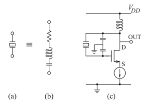
Figure \(\PageIndex{6}\): Crystal oscillator: (a) schematic symbol for a crystal; (b) its equivalent circuit; and (c) a FET crystal oscillator. The most commomly used form of a crystal oscillator is a Clapp oscillator because of the series LC electrical model of a piezolectric crystal.
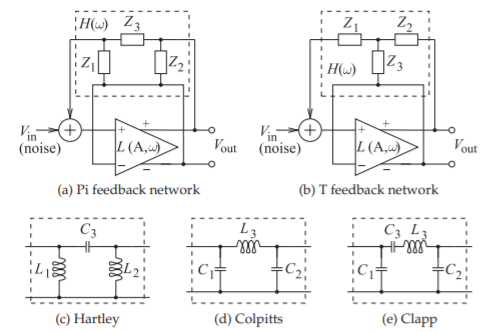
Figure \(\PageIndex{7}\): Differential feedback oscillator with Pi- and T-type feedback networks.
as it can absorb the parasitic capacitances of a transistor into the \(C_{1}\) and \(C_{2}\) capacitors, as in Figures \(\PageIndex{5}\)(a and c). The circuits shown in Figures \(\PageIndex{2}\)-\(\PageIndex{5}\) are the bases of nearly every microwave oscillator. Many modifications lead to better stability, compensate for transistor parasitics, and accommodate differential signaling.
Crystal references, for example, are commonly used for fixed-frequency oscillators, as the piezoelectric (usually quartz) crystals used have a very high \(Q\) and the oscillation frequency is very stable, typically to a few parts in a billion, and better if the crystal is temperature stabilized. A circuit with a crystal-based feedback loop creating a Clapp FET oscillator is shown in Figure \(\PageIndex{6}\). Common quartz reference crystals available as off-the-shelf components are \(10\text{ MHz},\: 20\text{ MHz},\) and \(40\text{ MHz}\) but are available up to \(300\text{ MHz}\). So they are not microwave oscillators but they are used as reference signals in a phase-locked loop to precisely set the frequency of microwave VCOs. Fixed-frequency microwave oscillators do not have this method available for stabilizing the oscillation frequency.
The Hartley, Colpitts, and Clapp networks are also widely used as the bases of oscillators in CMOS RFICs, where the feedback network is closely approximated using differential circuits [5, 6, 7, 8, 9, 10]. The basic differential configurations are shown in Figure \(\PageIndex{7}\).
Example \(\PageIndex{1}\): Common Emitter BJT Clapp Oscillator
Draw the schematic of a common-emitter BJT Clapp oscillator without biasing and then draw it with biasing.
Solution
The first step is defining the input and the output connections to be used in the oscillator configuration. There are several ways to do this and the solution here considers two configurations, \(\mathsf{Circuit}\:\mathsf{ A}\) and \(\mathsf{Circuit}\:\mathsf{ B}\).
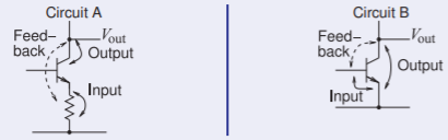
Figure \(\PageIndex{8}\)
Thus the possible common-emitter Clapp oscillators are (as in Figure \(\PageIndex{4}\) but with a BJT)
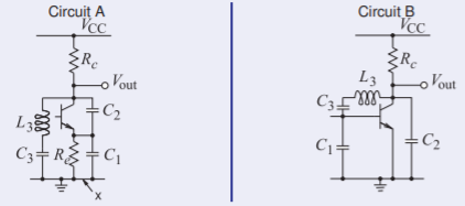
Figure \(\PageIndex{9}\)
In \(\mathsf{Circuit}\:\mathsf{ A}\) the point \(\mathsf{x}\) is the input terminal of the oscillator and the emitter terminal is the common point of the basic Clapp oscillator configuration. Appropriate bias must be applied to the base of the transistor. Also it would be good not to deliver power to \(R_{c}\) and instead deliver it to the load. In the circuits below a choke inductor \(L_{c}\), an open circuit at RF, is used to apply bias. \(L_{c}\) also enables a large output voltage swing. \(C_{c}\) is a large coupling capacitor and has very low impedance at RF and blocks DC.
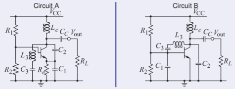
Figure \(\PageIndex{10}\)
Of these \(\mathsf{Circuit}\:\mathsf{ B}\) is the more attractive as the parasitic base-emitter capacitance will be absorbed into \(C_{1}\), and the parasitic collector-emitter capacitance will be absorbed into \(C_{2}\). Neither configuration can absorb the collector-base capacitance, \(C_{cb}\), so extra care must be made that \(C_{cb}\) does not result in instability.
Footnotes
[1] This description of oscillation, based on Equation \(\eqref{eq:3}\), is behind the erroneous Barkhausen stability criterion, which is also known as the Barkhausen oscillation criterion. Barkhausen himself used the criterion, known as the Barkhausen criterion, to establish the frequency of oscillation as \(L(A, \omega )H(\omega )=1\). This was misinterpreted as a stability or oscillation criterion. It is a necessary criterion for two-port feedback oscillation, but not sufficient. It does not indicate whether a system is unstable. Instead, the Nyquist criterion is the necessary and sufficient criterion for oscillation in feedback oscillators [1, 2, 3, 4]. The Barkhausen criterion should not be used in determining whether oscillation occurs.