
6.12: Problems
- Page ID
- 28564

Review Questions
1. What are the advantages of using an instrumentation amplifier versus a simple op amp differential amplifier?
2. How might an instrumentation amplifier be constructed from general purpose op amps?
3. What are the advantages of using programmable op amps?
4. What are the results of altering the programming current in a programmable op amp?
5. Give at least two applications for a high-power op amp.
6. Give at least two applications for a high-speed op amp.
7. What is an OTA?
8. How is an OTA different from a programmable op amp?
9. Give an application that might use an OTA.
10. Give at least three applications that could benefit from specialty linear integrated circuits.
11. Describe how a Norton amplifier achieves input differencing.
12. List a few of the major design differences that must be considered when working with Norton amplifiers versus ordinary op amps.
13. Explain why a current feedback amplifier does not suffer from the same gain-bandwidth limitations that ordinary op amps do.
Problems
Analysis Problems
1. An instrumentation amplifier has a differential input signal of 5 mV and a common-mode hum input of 2 mV. If the amplifier has a differential gain of 32 dB and a CMRR of 85 dB, what are the output levels of the desired signal and the hum signal?
2. Determine \(V_{out}\) in Figure \(\PageIndex{1}\) if \(V_{in+} = +20 mV\) DC and \(V_{in-} = -10 mV\) DC.
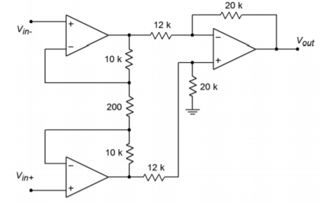
Figure \(\PageIndex{1}\)
3. Repeat Problem 2 for a differential input signal of 10 mV peak to peak.
4. Repeat Problem 3 for a differential input signal of 20 mV peak to peak and a common-mode signal of 5 mV peak to peak. Assume the system CMRR is 75 dB.
5. Determine the programming current in Figure 6.3.2 if \(R_{set} = 1 M\Omega\). Assume standard \(\pm\)15 V supplies.
6. Using an LM4250 programmable amplifier, determine the following parameters if \(I_{set} = 5 \mu A\): slew rate, \(f_{unity}\), input noise voltage, input bias current, standby supply current, and open loop gain.
7. Determine the voltage gain, \(f_2\), and power bandwidth (assume \(V_p\) = 10 V) for the circuit of Figure \(\PageIndex{2}\).
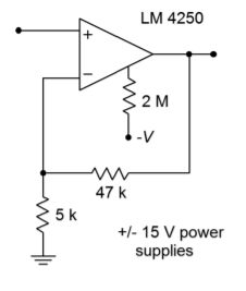
Figure \(\PageIndex{2}\)
8. The circuit of Figure \(\PageIndex{3}\) uses a light-dependent resistor to enable or disable the amplifier. Under full light, this LDR exhibits a resistance of 1 k\(\Omega\), but under no light conditions, the resistance is 50 M\(\Omega\). What are the standby current and \(f_{unity}\) values under full light and no light conditions?
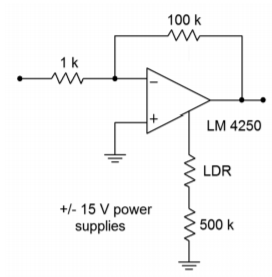
Figure \(\PageIndex{3}\)
9. Determine the required capacitance to set PSRR to at least 20 dB at 100 Hz for an LM386 power amp.
10. What is the power bandwidth for a 5 V peak signal in Figure 6.6.1?
11. Determine the device dissipation for an LM386 delivering 0.5 W into an 8 ohm load. Assume a 12 V power supply is used.
12. Determine the input resistance, output resistance and transconductance for an LM13700 OTA with \(I_{abc} = 100\) \(\mu\)A.
13. Determine the value of \(I_{abc}\) in Figure 6.7.2 if \(V_{control}\) = 0.5 V DC.
14. Recalculate the value of \(R_i\) for the circuit of Figure 6.8.4 if a voltage gain of 45 is desired.
15. Recalculate the input capacitance value for the circuit of Figure 6.8.4 if a lower break frequency of 15 Hz is desired.
Design Problems
16. Design an instrumentation amplifier with a gain of 20 dB using the LT1167
17. Utilizing the LM3900, design an inverting amplifier with a gain of 12 dB, an input impedance of at least 100 k\(\Omega\), and a lower break frequency no greater than 25 Hz.
18. Utilizing the LM3900, design a noninverting amplifier with a gain of 24 dB, an input impedance of at least 40 k\(\Omega\), and a lower break frequency no greater than 50 Hz.
19. Utilizing the CLC1606, design a noninverting amplifier with a gain of 6 dB
20. Utilizing the CLC1606, design an inverting amplifier with a gain of 12 dB.
Challenge Problems
21. Using Figure \(\PageIndex{1}\) as a guide, design an instrumentation amplifier with a differential gain of 40 dB. The system bandwidth should be at least 50 kHz. Indicate which op amps you intend to use.
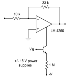
Figure \(\PageIndex{4}\)
22. Determine the gain, \(f_2\), power bandwidth (\(V_p = 10 V\)), and standby current for the circuit of Figure \(\PageIndex{4}\) if \(V_b= 0 V\), and if \(V_b = -15 V\).
23. Design a power amplifier with a voltage gain of 32 dB using the LM386.
24. Determine \(V_{out}\) in Figure 6.7.2 if \(V_{control} = 1 V DC \) and \(V_{in} = 100\) mV sine wave.
25. Sketch \(V_{out}\) for Figure 6.7.2 if \(V_{control}(t) = 1 \sin 2 \pi 1000 t\), and \(V_{in}(t) = 0.5 \sin 2 \pi 300,000 t.\)
26. Alter Figure 6.7.2 such that a 100 mV input signal will yield a 1 V output signal when \(V_{control}\) is +2 V.
27. Derive Equation 6.2.9 from the text.
Computer Simulation Problems
28. Use a simulator to verify the design produced in Problem 21.
29. Simulate the output of the circuit shown in Figure 6.8.4. Use a +15 V DC power supply with \(V_{in}(t) = 0.01 \sin 2 \pi 100 t\).
30. Use a simulator to verify the gain of the design produced in Problem 18.
31. Device mismatching can adversely affect the CMRR of an instrumentation amplifier. Rerun the simulation of the instrumentation amplifier (Figure 6.2.5) with a \(\pm\)5% tolerance applied to the value of \(R_{i}^{'}\) (Rip). Based on these simulations, what do you think would happen if all of the circuit resistors had this same tolerance?