
9.5: Problems
- Page ID
- 28571

Review Questions
1. How does positive feedback differ from negative feedback?
2. Define the Barkhausen criterion.
3. Explain the operation of the Wien bridge op amp oscillator.
4. Detail the operation of the phase shift op amp oscillator.
5. How might a square wave be generated from a sinusoidal or triangular source?
6. Give two ways to make the output frequency of a Wien bridge oscillator user-adjustable.
7. What factors contribute to the accuracy of a Wien bridge oscillator's output frequency?
8. What is a VCO, and how does it differ from a fixed-frequency oscillator?
9. Draw a block diagram of a PLL and explain its basic operation.
10. What is the difference between capture range and lock range for a PLL?
11. Give at least two applications for a fixed-frequency oscillator or VCO.
12. Give at least two applications for the PLL.
13. Explain the difference between astable and monostable operation of a timer.
Problems
Analysis Problems
Unless otherwise specified, all circuits use \(\pm\)15 V power supplies.
1. Given the circuit of Figure \(\PageIndex{1}\), determine the frequency of oscillation if \(R_1 = 1.5 k\Omega \), \(R_2 = R_3 = R_4 = 3 k\Omega \), and \(C_1 = C_2 = 22 nF\).
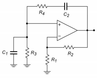
Figure \(\PageIndex{1}\)
2. Given the circuit of Figure \(\PageIndex{1}\), determine the frequency of oscillation if \(R_2 = 22 k\Omega \), \(R_1 = R_3 = R_4 = 11 k\Omega \), and \(C_1 = C_2 = 33 nF\).
3. Given the circuit of Figure \(\PageIndex{2}\), determine the maximum and minimum fo if \(R_1 = 5.6 k\Omega \), \(R_2 = 12 k\Omega \), \(R_3 = R_4 = 1 k\Omega \), \(P_1 = P_2 = 10 k\Omega \), \(C_1 = C_2 = 39 nF\).
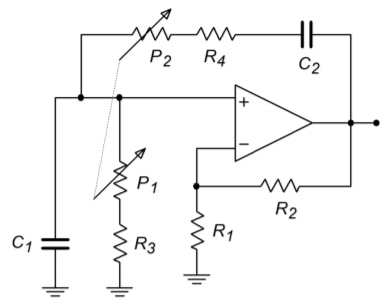
Figure \(\PageIndex{2}\)
4. Given the circuit of Figure \(\PageIndex{3}\), determine fo if \(R_4 = 2 k\Omega \), \(R_3 = 20 k\Omega \), \(R_2 = 200 k\Omega \), \(R_1 = 1.6 M\Omega \), \(C_1 = 30 nF\), \(C_2 = 3 nF\), \(C_3 = 300 pF\).
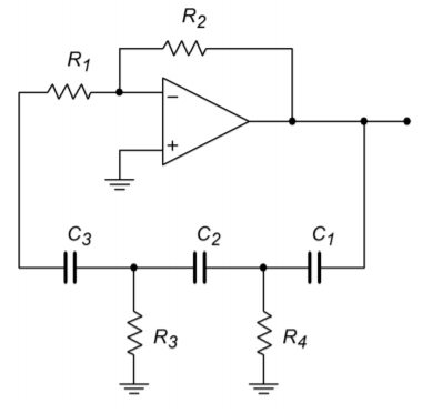
Figure \(\PageIndex{3}\)
5. Given the circuit of Figure \(\PageIndex{3}\), determine \(f_o\) if \(R_1 = R_3 = R_4 = 3.3 k\Omega \), \(R_2 = 100 k\Omega \), \(C_1 = C_2 = C_3 = 86 nF\).
6. Given the circuit of Figure \(\PageIndex{4}\), determine \(f_o\) if \(R_1 = R_2 = 22 k\Omega \), \(R_3 = 33 k\Omega \), \(C = 3.3 nF\).
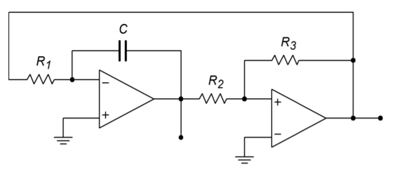
Figure \(\PageIndex{4}\)
7. Using the circuit of Figure \(\PageIndex{5}\), determine the output voltage if \(R_{set} = 100 k\).
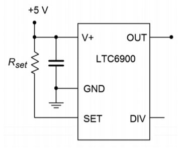
Figure \(\PageIndex{5}\)
8. Using the circuit of Figure \(\PageIndex{6}\), determine the output voltage if \(R_{set} = 50 k\).
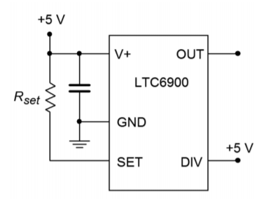
Figure \(\PageIndex{6}\)
9. A temperature dependent resistor, or thermistor, is used in Figure \(\PageIndex{7}\). If the resistance varies between 20 k and 200 k through the temperature range of interest, determine the range of output frequencies.
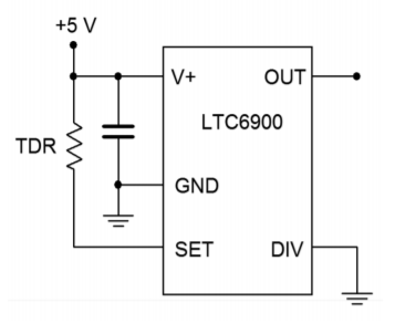
Figure \(\PageIndex{7}\)
10. For the circuit of \(\PageIndex{8}\), determine the range of output frequencies if \(V_C\) varies between 0 V and -1 V. \(R_C = 100 k\), \(R_1 = 1 M\), \(R_2 = 681 k\).
11. For the circuit of Problem 9.10, determine the output frequencies if \(V_c\) is a 100 Hz square wave at 0.5 volts peak.
12. Sketch the output waveform for Problem 9.11.
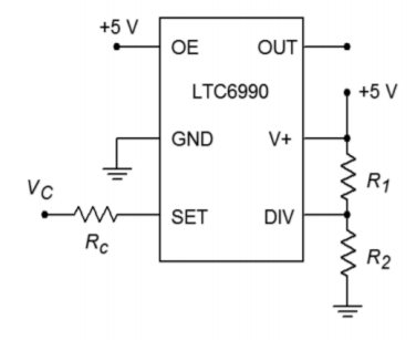
Figure \(\PageIndex{8}\)
13. If a control voltage of 0.4 sin 2π60t is used for the circuit of Problem 9.10, find the resulting maximum and minimum output frequencies.
14. Given the circuit of Figure \(\PageIndex{9}\), determine the output frequency if \(V_C = 2 V\), \(R_{VCO} = R_{set} = 100 k\), \(R_1 = 976 k\) and \(R_2 = 102 k\).
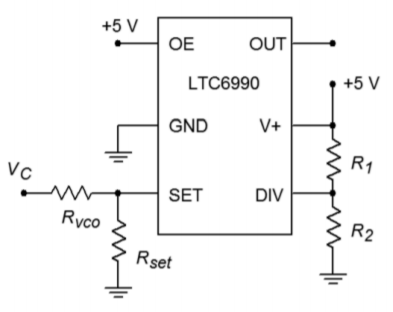
Figure \(\PageIndex{9}\)
15. Given the circuit of Figure \(\PageIndex{4}\), determine fo if \(R_1 = R_2 = 22 k\Omega \), \(R_3 = 33 k\Omega \), and \(C = 3.3 nF\).
16. Determine the output frequency range in Figure \(\PageIndex{10}\) if \(V_C\) varies from 0 to 2 volts, \(R_f = 200k\), \(R_i = 100 k\), \(R_C = 500 k\), \(R_1 = 976 k\) and \(R_2 = 182 k\).
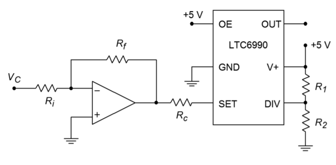
Figure \(\PageIndex{10}\)
17. Determine the output frequency range in Figure \(\PageIndex{11}\) if \(V_b\) varies from 0 to 2 volts, \(V_a = 1 volt\), \(R_f = 200 k\), \(R_a = 100 k\), \(R_b = 200 k\), \(R_C = 390 k\), \(R_1 = 182 k\) and \(R_2 = 976 k\).
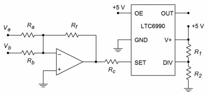
Figure \(\PageIndex{11}\)
Design Problems
18. For the circuit of Figure \(\PageIndex{1}\), determine values for \(C_1\) and \(C_2\) if \(R_1 = 6.8 k\Omega \), \(R_2 = R_3 = R_4 = 15 k\Omega \), and \(f_o = 30 kHz\).
19. For the circuit of Figure \(\PageIndex{1}\), determine values for \(R_3\) and \(R_4\) if \(R_1 = 2.2 k\Omega \), \(R_2 = 4.7 k\Omega \), \(C_1 = C_2 = 47 nF\), and \(f_o = 400 Hz\).
20. For the circuit of Figure \(\PageIndex{1}\), determine values for \(R_2, C_1\) and \(C_2\) if \(R_1 = 7.2 k\Omega , R_3 = R_4 = 3.9 k\Omega \), and \(f_o = 19 kHz\).
21. Determine the values required for \(R_3, R_4, P_1\), and \(P_2\) in Figure \(\PageIndex{2}\) if \(C_1 = C_2 = 98 nF\), \(R_1 = 5.6 k\Omega , R_2 = 12 k\Omega \), \(f_{o.min} = 2 kHz\), and \(f_{o.max} = 20 kHz\).
22. Repeat Problem 21 for \(f_{o.min} = 10 kHz\) and \(f_{o.max} = 30 kHz\).
23. Redesign the circuit of Problem 1 so that exact gain resistors are not needed. Use Figure 9.6 as a model.
24. Redesign the circuit of Problem 3 so that clipping does not occur. Use Figure 9.2.6 as a model.
25. Determine new values for the capacitors of Problem 4 if fo is changed to 10 kHz.
26. Given the circuit of Figure \(\PageIndex{3}\), determine values for the capacitors if \(R_1 = R_3 = R_4 = 3.3 k\Omega \), \(R_2 = 100 k\Omega \), and \(f_o = 7.6 kHz\).
27. Given the circuit of Figure \(\PageIndex{3}\), determine values for the resistors if the capacitors all equal 1100 pF and fo = 15 kHz.
28. Determine the capacitor and resistor values for the circuit of Figure \(\PageIndex{3}\) if \(R_2 = 56 k\Omega \) and \(f_o = 1 kHz\).
29. Find C in Figure \(\PageIndex{4}\) if \(f_o = 5 kHz, R_1 = R_3 = 39 k\Omega , R_2 = 18 k\Omega \).
30. Determine the resistor values in Figure \(\PageIndex{4}\) if \(f_o = 20 kHz\) and \(C = 22 nF\). Set \(R_1 = R_2\) and \(R_2 = R_3/2\). Sketch the output waveforms as well.
31. Determine the required ratio for \(R_2/R_3\) to set the triangle wave output to 5 V peak in Figure \(\PageIndex{4}\).
32. Using the circuit of Figure \(\PageIndex{5}\), find \(R_{set}\) for an output of 100 kHz.
33. Determine the value for \(R_{set}\) in Figure \(\PageIndex{6}\) to set the frequency to 50 kHz.
34. Design a square wave generator that is adjustable from 5 kHz to 20 kHz.
35. For the circuit of Figure \(\PageIndex{9}\), determine the component values such that a frequency of 250 kHz is produced when \(V_C = 0\) volts and 125 kHz when \(V_C\) is 1 volt.
36. Design a \(V_{CO}\) circuit and determine the component values such that a frequency of 250 kHz is produced when \(V_C = 1\) volt and 125 kHz when \(V_C\) is 0 volts.
Challenge Problems
37. Using Figure 9.2.9 as a guide, design a sine wave oscillator that will operate from 2 Hz to 20 kHz, in decade ranges
38. Design a 10 kHz TTL-compatable square wave oscillator using a Wien bridge oscillator and a 311 comparator.
39. Using a triangle or sine wave oscillator and a comparator, design a variable duty cycle pulse generator. Hint: Consider varying the comparator
reference.
40. Using a function synthesizer (Chapter Seven) and the oscillator of Figure \(\PageIndex{4}\), outline a simple laboratory frequency generator with sine, triangle, and square wave outputs.
41. For the preceding problem, outline how amplitude and DC offset controls could be implemented as well.
42. Generate a square wave that smoothly increases from 50 kHz to 300 kHz and back at a rate 100 times each second.
43. Assume that the output of the left-most op amp of Figure \(\PageIndex{4}\) drives Vb of Figure \(\PageIndex{11}\). Further, assume that a positive DC voltage equal to the peak
value of \(V_b\) is used to drive \(V_a\). Also, \(R_a = R_b = R_f\). Assuming the frequency produced by Figure \(\PageIndex{4}\) is considerably lower than that of Figure \(\PageIndex{11}\), describe the output waveform of Figure \(\PageIndex{11}\).
Computer Simulation Problems
44. Perform a simulation of the circuit of Problem 1. Perform a frequency domain analysis of the positive feedback loop's gain and phase, and verify that the Barkhausen Criterion is met.
45. Perform a simulation for the circuit of Problem 4. Perform a frequency domain analysis of the positive feedback loop's gain and phase, and verify that the Barkhausen Criterion is met.
46. Perform a time-domain simulation analysis for the circuit of Problem 6. Make sure that you check both outputs (a simultaneous plot would be best).