
11.11: Voltage-Controlled Filters (Extended Topic)
- Page ID
- 28516

A voltage-controlled filter, or VCF, is nothing more than a standard filter whose tuning frequency is controlled by an external voltage. You might think of this concept as an extension of the clock control aspects of the switched capacitor filter. VCFs are used in a wide range of applications including instrumentation devices such as swept frequency analyzers and music synthesizers. Any application that requires precise or rapid control of tuning frequency calls for a VCF. Virtually any of the filters presented in this chapter may be turned into VCFs. All you need to do is substitute the tuning elements of the filter with a voltage-controlled version. Typically, this means replacing the tuning resistors with voltage-controlled resistances.
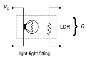
Figure \(\PageIndex{1}\): A photoresistor/lamp used as a variable resistance.
Two possible ways of creating a voltage-controlled resistance include the photoresistor/lamp combination (Figure \(\PageIndex{1}\)), and the use of an FET in its ohmic region (Figure \(\PageIndex{2}\)). To use these items, simply remove the tuning resistor(s), and replace them with a voltage-controlled resistance. As an example, a simple single-pole high-pass VCF is shown in Figure \(\PageIndex{3}\). As the control voltage (\(V_c\)) increases, the lamp brightness increases causing the photoresistor's value to drop. Because the photoresistor sets the tuning frequency, the net result is an increase in \(f_c\). The FET version produces a resistance that is proportional to the magnitude of the gate voltage (\(V_c\)).
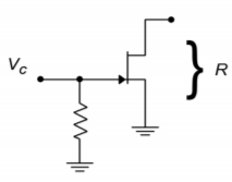
Figure \(\PageIndex{2}\): Using a JFET in the ohmic region.
These two solutions are not without their problems. In the case of the lamp/photoresistor, response time is not very fast, and the lamp portion requires a fairly large drive current. The FET circuit eliminates these problems, but requires that the voltage across it remain fairly low (usually less than 100 mV). Larger signal swings will drive the FET out of the ohmic region, and distortion will increase dramatically. Also, the popular N channel variety requires a negative gate potential, which is generally not preferred. In both cases, one more problem remains: it is difficult to create a wide linear control range.
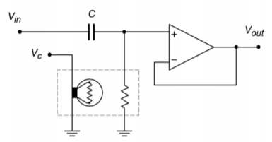
Figure \(\PageIndex{3}\): Variable resistance connection for VCF.
Another way to create the effect of a voltage-variable tuning element is through the use of an operational transconductance amplifier, or OTA (see Chapter Six). Remember, this device is essentially a voltage-to-current converter. Its output current is a function of its control current. (The control currrent is easily derived from a control voltage and resistor.) This device is ideally suited to “inverting” type inputs, where an input resistor is used as a voltage-to-current converter. One possible example is shown in Figure \(\PageIndex{4}\), a state-variable VCF. The boxed sections show where an OTA has replaced a standard single resistor. In this circuit, a large control voltage creates a large control current, thus increasing transconductance. This simulates a smaller tuning resistor value, and thus creates a higher tuning frequency. The OTA approach proves to be reliable, repeatable, and generally low in cost. It also offers a fairly wide linear tuning range.
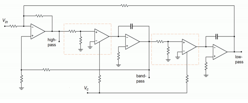
Figure \(\PageIndex{4}\): Using OTAs as a controlled element in a VCF.