
5.4: RC Band-Pass Filter
- Page ID
- 7652

The circuit shown in Figure \(\PageIndex{1}\) consists of a low-pass filter stage to the left of the voltage follower, and a high-pass filter stage to the right. [The functioning of a high-pass filter is illustrated in homework Problem 5.4.2]. As indicated on Figure \(\PageIndex{1}\), the currents in the two stages are independent of each other, by virtue of the buffering due to the voltage follower. Therefore, the simple ODEs for each type of 1st order filter are still valid for the two-stage circuit of Figure \(\PageIndex{1}\), with mid-circuit voltage \(e_{m}(t)\) being the quantity shared by the two stages, as the output from the low-pass stage and the input to the high-pass stage. These ODEs are Equation 5.2.7 for the low-pass filter,
\[\tau_{L} \dot{e}_{m}+e_{m}=e_{i}, \quad \tau_{L}=R_{L} C_{L}\label{eqn:5.16} \]
and the ODE derived in homework Problem 5.4.1 for the high-pass filter,
\[\tau_{H} \dot{e}_{o}+e_{o}=\tau_{H} \dot{e}_{m}, \quad \tau_{H}=R_{H} C_{H}\label{eqn:5.17} \]
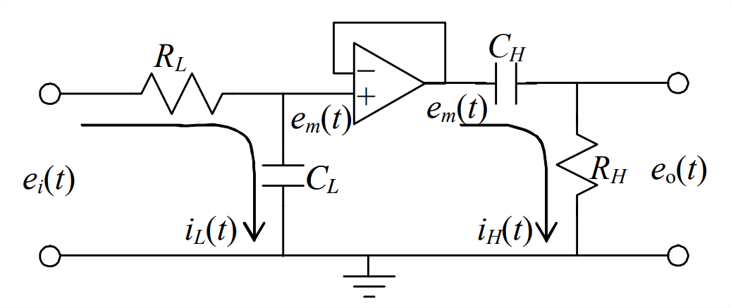
An equation such as Equation \(\ref{eqn:5.17}\) is described as having “right-hand-side (RHS) dynamics” because the right-hand-side includes a derivative of the input (\(\dot{e}_{m}\) in this case), rather than just the undifferentiated input itself.
The combination of these two 1st order circuits turns out to be a 2nd order system, and we shall re-visit this subject in Sections 9.10 and 10.4. We consider the RC band-pass filter circuit now because it illustrates (1) application of a voltage follower, and (2) the important physical characteristic of op-amps that is described next.
Note in Figure \(\PageIndex{1}\) that the feedback wire across the op-amp connects directly to the negative input port; this port has essentially infinite resistance, so there cannot be any current in the feedback wire. But Figure \(\PageIndex{1}\) also shows the non-zero, second-stage current \(i_{H}(t)\) downstream of the op-amp; this appears to contradict the claim of zero feedback current in the op-amp, since the graphical representation of the op-amp suggests that the feedback wire is continuous electrically with the downstream circuit. In fact, the standard graphical representation of an op-amp with negative feedback, such as that in Figure \(\PageIndex{1}\), is oversimplified to the point of being misleading. For an actual op-amp (as opposed to the standard graphical representation), the downstream current is not continuous with the feedback current, but instead, is completely independent. In fact, the current downstream of an op-amp is determined only by the output voltage of the op-amp and the downstream electrical components, for example, the second-stage capacitor and resistor in Figure \(\PageIndex{1}\). The technical characteristic of an op-amp that permits this independence of currents is very low output impedance (Horowitz and Hill, 1980, pages 25, 92-95, and 105). For another example of the independence of feedback and downstream currents, see homework Problem 5.10.