
4.5: Safety Features in Piping and Instrumentation Diagrams
- Page ID
- 22386

Introduction
Safety has become integral to the manufacturing world. The implementation of proper safety techniques and accident prevention can not only save time and money, but prevent personal injury as well. P&IDs, when properly utilized, are a powerful resource to identify safety hazards within the plant operations. The following sections provide an overview for the safety hazards that exist within a process, and illustrate the importance of P&IDs in a chemical plant.
Safety in Design
During the early stages of plant design it is critical to determine important safety features that remove potential hazards from effecting the facility environment. Regulations require that plant designers play a major role in minimizing the risks associated with these hazards. However, in order to do so, designers need to be aware of the hazards that exist during plant activity. The facility design team must develop a detailed drawing (P&IDs) including specifications of the plant process and environment to ensure that every aspect with regards to safety is covered.
Hazard vs, Risk
When discussing safety, the terms hazard and risk are often used interchangeably. However, the difference in definition between the two terms is critical in utilizing the information they provide in increasing the safety within a plant. Hazard is defined as a potential source of danger and risk is defined as the level of threat associated with the hazard. A risk of a hazard occurring can be represented mathematically by the following equation:
\[\text {Risk}=\text {Frequency} \times \text {Consequences} \nonumber \]
Frequency represents the probability that a hazard will occur, and consequence represents the impact of that hazard. Values for each parameter of the equation above are assigned by using either experimental information or educated judgment based on engineering models and experience. Each plant design process will have specific safety hazards and risks associated with it. Therefore, there is no predetermined value that can be assigned to each variable. For example, in one situation, a water tower may be well supported inside the plant facility, and in another situation a water tower of similar structure may be hoisted against a rusted frame work outside of the plant facility. Both of these situations have different levels of risk associated with them. Needless to say, the risks associated with a plant setup can be reduced substantially by minimizing the probability that a hazard will occur.
Hazard Locations and Risk Hotspots
Common hazard locations exist in any place containing large amounts of energy. The degree of danger is proportional to the amount of energy stored at that location. Risk can be directly linked to kinetic energy, potential energy, work, heat, enthalpy and internal energy sources. Kinetic energy, otherwise known as energy in motion, is present in any moving component. The component may be vibrating, rotating, or translating, and this motion causes the kinetic energy of that part to greatly increase. Within industry, personal injuries and fatalities are common hazards associated with moving parts. Reactors and cooling towers placed in high locations contain potential energy. If a structural failure were to occur within a plant, these structural units and their contents could fall from a large elevation onto another processing system or a human being, releasing all the chemical contents stored inside. Similarly, the stored work in springs and other devices can cause fatigue and wear on the mechanical system over time, and result in eventual machine failure. Heat released from a reaction within a chemical reactor can be rapid and fatal if not accounted for. The buildup of heat can cause serious consequences with runaway reactions and boiler explosions. The enthalpy and internal energy of a reaction typically are the cause of most runaway reactions and destructive fires in a plant.
Risk Hotspots
Uncontrolled chemical hotspots created within a chemical plant are a common source of hazard, besides the hazard locations pertaining to energy sources such as kinetic and potential energy. Risk hotspots mostly occurs in the piping system and associated valves of the system, joints, traps, and various other piping elements. Possible malfunction of the system due to structural corrosion can be triggered by the failure to maintain the piping systems efficiently and periodically. Even if one of the valves in the system has corroded and is unable to function properly, the fluid flowing through the pipe might get trapped, and the resultant buildup of pressure in the pipe may cause major safety hazards including fatal ones such as an explosion. If the system is not shut off before the pressure gets out of control, the pressure buildup in the pipe will cause it to burst, releasing all of its internal contents to the surrounding environment.
Storage vessels are other pieces of equipment that must be cared for properly. Since the plant operators and engineers do not usually interact with the storage vessels, as compared to other parts of the plant process such as the piping system, they are considered to be of secondary importance and commonly overlooked. Storage vessels have much more content inside them than pipes, so a leak or a burst would take longer to get back under control than pipes, which can by plugged more easily. Problems which may arise from storage vessels are not associated with their design, but in fact from not thoroughly and periodically maintaining them. Possible complications that can arise from neglecting the storage tanks are over-pressurization, overfilling, heating element malfunction, or simply equipment malfunction.
Chemical reactors are another common location where risk hotspots occur. The nature and design of commercial chemical reactors is to handle a controlled explosion. However, if the control element is removed, disaster is bound to occur, just as in any other part of the chemical plant. The most common type of hazard is a runaway reaction inside a batch reactor. When the plant facility looses electricity or cooling water, a runaway reaction will strike inside the reactor. Once a runaway reaction has spun up inside the reactor, many other hazards may follow, such as flow reversal in the pipes, incorrect reagent charging, heat exchanger failures, and external fires. Other hazards may perhaps be even more serious, such as engineering errors that could potentially cause a runaway reaction to occur, including inappropriate material selection, inadequate equipment inspection or failure to fully understand the chemistry or exothermic nature of a reaction. A runaway reaction originating inside the chemical reactor can easily cause a chain reaction across the rest of the equipment at the facility, and can result in the entire system malfunctioning.
Other process equipment that may be hazardous and where risk hotspots commonly arise, are vacuum operators, furnaces, pumps, gas movers, compressors, and heat exchangers. The location and type of specific piping and unit operations are available on the process P&ID. A responsible process engineer should use the P&ID to identify all risk hotspots, and act accordingly to monitor and maintain a safe working environment. In addition, a standardized plan should be constructed so that in the event of a malfunction, the correct steps can be taken to bring the faulty part back under control. Supplementary precautions should be taken to prevent a comparatively minor malfunction in the system from becoming a disaster which may violate environmental regulations and even endanger human lives.
Safe Design Principles
The ISD or Inherently Safer Design movement was a doctrine striving for safer chemical processing procedures. This movement was pioneered by Trevor Kletz in 1976, and promotes the design of processes so safe, that no catastrophic failure can occur within the plant. The following principles apply to initial process design:
- Use the fewest number of hazardous substances in the smallest quantities and still maintaining plant productivity
- When possible, substitute hazardous chemicals with chemicals that are less dangerous
- Practice moderate operating conditions in the plant
- Use the simplest plant design possible
- Design equipment in the plant to minimize the effects of a hazardous incident
The specifications determined by the process designers are communicated through the P&ID.
Hazards in Construction
In order to eliminate hazards, a operations personnel must be able to identify that a hazard exists. Hazards that may be encountered on plant sites may be categorized into three main types:
- Hazards harmful to health: When workers are exposed to or come in contact with asbestos, corrosives, irritants, toxins, or noxious gases try to avoid by specifying the processes, which lead to this exposure
- Hazards likely to cause personal injury: Hazard awareness is increased when people have to work in situations likely to expose them to the risk of personal injury, including moving plant machinery or working in areas where objects are likely to fall. Situations where there are live electrical circuits overhead, buried power lines, and confined working conditions are likely to cause personal injury.
- Hazards likely to lead to a catastrophic event: These hazards have consequences beyond the site boundary. They include fire outbreaks, explosions, flooding, or premature collapse of structures, cranes, tunnels and excavations.
Fail-Safe Design
The fail-safe design of a unit operation (such as a reaction vessel) requires a complete understanding of the operation at hand, and the knowledge of all the worst-case conditions. A fail-safe system is a unit operation such that, if any or all of the worst-case conditions were to occur, the operation would shut itself down automatically and in a safe fashion. In the case of a run-away reaction, if reagent feed limits, interlocking controls, and integrated heat balances are all properly maintained, the reaction cannot "run away." Other precautions such as purges, vents, dump tanks and quenches are available for reaction vessels, and should be visible on the P&ID.
Inherent Safer Predesign
The table below provides a guideline for identifying and minimizing hazards partly based upon Kletz's rules for ISD in the Safe Design Principles section above. The step/rule column describes the action taken. The tools column describes the mechanism by which the actions are taken. The experimental and analytical resources column describes the knowledge by which the mechanisms are created. The Literature References column describes where the knowledge can be found.
| Step/Rule | Tools | Experimental and Analytical Resources | Literature References |
|---|---|---|---|
| 1. Identify | Fire triangle, Flammability-limit chart, Chemical reactivity chart, Safety compatibility chart, Safety stream chart, Toxicity ratings | Thermodynamic calculations, Reactor design equations, calorimetry, flammability charts | Perry's Handbook (10) Table 26-10 and associated pages |
| 2. Eradicate (ISD Rule 2) | Inert-gas blanketing, Failsafe design | see above | see above |
| 3. Minimize, Simplify, Moderate, Attenuate (ISD Rules 1, 3, 5) | Moderate ignition sources, Keep reactive volumes small | Logical chemical engineering analytical and computational skills | Merk Index, MSDSs, Chemical Engineering textbooks and monographs |
| 4. Isolate (ISD Rule 4) | Separate hazardous operations - Surround in an impenetrable structure | Logical chemical engineering judgment |
Relief Systems
Organizations such as the American Society of Mechanical Engineers, American Petroleum Institute and National Fire Protection Association layout recommendations and design standards so that most engineers with proper training can setup proper emergency relief systems for single phase flow. Unfortunately, this is often not good enough for reactive systems. These systems are much more complex and include multiple phase flow, runaway reaction potential and self reactant material. When designing an emergency relief system (ERS) it is necessary to understand all aspects of the chemicals and processes that will be in play. This includes but is not limited to: kinetics of the possible reactions, contamination, interactions with air, rust, piping, or water, phase changes and runaway reactions. The follwing topics deal with the hazards that require designing relief systems and the prevention of runaway reactions.
Planning and Design
When designing an ERS, it is important to consider the worst-case scenario. This is based upon a thorough knowledge of the reactions, materials, and environment of the process. Some of the most critical scenarios are over-pressurization in a reactor.
All disaster scenarios can be analyzed using a hazard and operability (HAZOP) study. This HAZOP study will analyze a process based upon human, equipment, and environmental factors.
The HAZOP team must take the following steps to ensure that all potential scenarios are taken into account:
- Review the potential hazards of all chemicals. This includes non-operational conditions and interactions with contaminants
- Study the chemical process including all possible reactions, rearrangements, decompositions, etc.
- Review the P&ID’s for the process
- Study the specific reactor and storage vessels for material composition compatibility, size, surface area, instrument ranges, and set points
With this information, the HAZOP team can determine most of the potential disaster scenarios. Most likely the worst case scenario will involve fire induced runaway reactions.
Design Strategies
There are various techniques often used to prevent failure from over-pressurization, fire, runaway reaction or other disaster scenarios. The following are some design suggestions that will decrease this risk:
- The use of insulation in case of fire. Unfortunately, insulation will also minimize heat loss from the reactor during a runaway reaction. It is important to consider the ability of a vessel to drain when using insulation. If the contents can be drained and cooled before the reaction starts to runaway, catastrophe can be prevented.
- Design to avoid fire damage on sensitive equipment. The possibility of fire damage on electrical equipment or sensors will cause control difficulties when trying to slow down a runaway reaction, or monitor another emergency situation.
- Consider the structural integrity of the entire system due to fire damage.
- Use multiple purge streams and valves to separate materials. Separating reaction components into a storage vessel with a large surface area will allow for faster cooling.
- Install two separate relief devices in case one has been compromised due to fouling or solid particle blockage.
Overall safety relief plans must be made for all possible scenarios.
Reaction Kinetics
Reaction kinetics usually determine the potential for safety disaster. For the average exothermic reaction, the reaction rate doubles with every 10°C increase. This will lead to an exponential increase in energy which will force both the temperature and pressure in a system to uncontrollable levels. Since reaction rates are sensitive not only to temperature, but also pressure, contaminants, concentrations and phases, all possibilities must be adequately analyzed for plant operation to be deemed safe.
Relief devices should be designed to handle chemicals and/or mixtures in any phase. For example, if a reactor temperature increases suddenly and a safety relief valve is activated the material must be able to flow through the valve quickly and safely. If the chemical has changed phases, or has a higher pressure that the valve cannot accommodate, the chemical will not be able to escape and build up pressure in a reactor. This would greatly increase the risk of a disaster. Because of the extent of possibilities when considering reaction rates and kinetics, it is usually necessary to consult some sort of computer simulation or dynamic simulation tool to plan for every possible scenario.
Runaway Reactions
Runaway reactions are caused when exothermic reactions are fed more energy due to malfunctioning cooling systems. This causes an exponential increase in temperature, which in turn causes an increase in pressure, and finally damage to the reactor and/or plant. The possibility of malfunctioning cooling systems must always be considered for flammable materials. If materials are being stored at temperatures above their flash point, fire is always a possibility. Fire will cause a reaction to reach runaway conditions with very little reactant. Relief systems for fire induced runaway reactions must be larger than conventional runaway reactions.
While relief systems are often designed for over-pressurization, this might not be enough when considering flammable materials. Constant or prolonged exposure to flame will cause most normal reactant or storage vessels to fail causing chemical leaks or plant fires. Fire proof insulation must be used together with normal pressure relief systems to prevent system failure. An important design variable when considering fire induced runaway reactions is fire flux. This variable considers heat impact on a reactor due to fire. Formulas for calculating fire flux can be obtained from the National Fire Protection Association. The elevation of flames must also be considered when designing reactor vessels and safety relief systems. Pool fires can produce flames that are hundreds of feet high; using the P&ID will be important in ensuring that process components sensitive to fire are sufficiently protected from something like pool fires.
Two Phase Flow
For systems in which multiple phase flow is possible, all phases must be planned for. For vapor hybrid systems, all-vapor flow should be considered. Likewise, when foam flow is possible, all-foam flow should be planned for. This is all part of the mindset of planning for the worst case scenario. The most conservative design should always be used when faced with uncertainties of phase flow.
Often times, a runaway reaction will cause high-viscosity two phase flow. Relief valves and safety features must be ready for viscous flow. Many resources suggest averaging the viscosities of the two phases to plan for two phase flow. It is important to keep in mind however, that two phase flow discharge will separate in the discharge line. This will lead to higher pressure drop. Piping sizes are often underestimated due to this unplanned scenario. Undersized piping will lead to valve rupture and back pressure and could cause venting disturbances during the emergencies where venting is critical to the safe shutdown of a process.
Regulations
There are often conflicts and contradictions in federal regulations and recommended practices for safety design guidelines. When faced with such confusion the designer should at least design to the level of the Occupational Safety and Health Administration's (OSHA) requirements, as well as meeting regulations set by the Environmental Protection Agency (EPA), the Process Safety Management(PSM), and the Risk Management Program (RMP). While these guidelines and regulations produce a minimum standard to follow, when dealing with reactive systems, this does not always meet process needs. For more details on the various regulatory agencies that govern chemical processes, see Regulatory Agencies and Compliance.
Additional Safety Hazards in Chemical Plants
This section outlines potential safety hazards commonly found in places where chemicals are stored or chemical processes are taking place. While these hazards are rather easily prevented through attention to detail and general awareness, neglecting them can have catastrophic consequences.
Time Sensitive Chemicals
Some chemicals have a "shelf life," or an expiration date provided by the manufacturer. The chemical must be used by this date or properly discarded. These are typically reactive chemicals, which can become unstable after a certain period of time, possibly rupturing the vessel in which they are stored. An example of this is a monomer that begins to polymerize unless an inhibitor is present. This inhibitor is completely consumed after a certain period of time, allowing polymerization to occur, and therefore must be used or discarded by that time. Another example deals with the formation of peroxide, which can be a severe fire and explosion hazard. It may also be a health concern, causing severe mucous membrane, respiratory tract, skin, and/or eye burns. Peroxide-forming materials should be stored carefully, labeled with the date received and the date first opened on the container. Chemicals should be disposed of or checked for peroxide formation after six months; do not open any container with solid formation around the lid. There are several ways to prevent this from happening. Material Safety and Data Sheets (MSDS) should be available for any chemical the plant uses. These can inform you if a particular chemical becomes unstable after a certain period of time. It is also important to make sure there are procedures in place for handling time-sensitive materials. Lastly, investigating near-miss occurrences can help to ensure that future incidents do not occur.
Pressure Relief Systems
Any open pipe in a chemical plant is a potential discharge site. While operator convenience and maintenance remains a concern, safety takes precedence when dealing with relief systems. It is essential to operator safety that relief valve discharge sites are located in areas that pose a low risk of exposing personnel to chemical hazards and are directed away from all access platforms. It is common in industry to tie multiple pressure relief devices to an emergency vent header that releases on the roof of the plant. Long stretches of unsupported pipes also pose a potential threat. Force generated by material flow could bend or break the pipe impeding on plant operations, and more importantly, injuring personnel.
Dust Explosion Hazards
Most flammable solids can form an explosive dust cloud if the particles are small enough. Materials such as wood, grain, sugar, plastics, and many metals can all form these explosive dust clouds. Dust explosions occur when a combustible material accumulates in a confined area and is exposed to an ignition source. High risks areas are usually those that are neglected such as tops of vessels and tanks, on pipes, storage bins, bucket elevators, and dust collectors.
To prevent dust explosions, it is essential to implement good housekeeping practices. Care must be taken so that the cleaning process, such as sweeping, doesn't turn a dust layer into a more dangerous cloud. Operations and process engineers should be aware of all the mechanical and safety control equipment associated with preventing fires. Equipment like electric vacuums must be appropriate for use in an area where an explosive dust cloud could form. This entails no holes or cracks in the cord, sufficient grounding, and receiving site approval for use of the equipment.
Overfilling Tanks
The overfilling of vessels has long been a leading cause of serious incidents in chemical and petroleum industries. When a level sensor or high-level alarm fails, reactive material can spill over the tank and accumulate. If this material is exposed to an ignition source, there is the potential for an explosion, leading to serious property damage, environmental issues, and injury to operations personnel. When filling or draining a tank with material, operators should be aware of all relevant level, pressure and temperature controls in place, and watch for abnormal trends. Also, all safety critical alarms surrounding a vessel should be tested regularly at frequencies recommended in plant process-safety-management procedures. Conducting regular process maintenance on safety critical alarms have numerous benefits, which include reducing the risk of operating a plant with faulty equipment, and increasing operator awareness with the location and function of critical safety devices.
Containing Storage Tank Spills
Engineering controls are implemented into plant designs to account for potential disasters, such as a spill, leak, or complete emptying of a storage tank. Industrial-sized chemical plants store large amounts of raw materials, products, and byproducts on-site. The amount of each varies, but is typically between three to thirty (or more) days of the required supply or amount produced. The stored chemicals can be hazardous, flammable, explosive, and/or reactive with each other. In the event of a tank spilling, dikes are built around tanks to contain the spill and protect the surrounding community from the spill. The regulations of the dikes include the following: dike volume must be 1.5X the largest storage tank contained by the dike, reactive materials cannot be stored in the same dike, and scuba gear must be present on-site if any dike is deeper than four feet. Since the dikes cannot contain any reactive materials, the implementation of dikes affects the overall plant layout. Typically, dikes are designed to be like speed bumps and have a height less than one foot so fork-lifts and tankers can easily maneuver through the plant. Dikes are an effective engineering control that greatly improve the safety of a chemical plant.
Temperature and Pressure Ratings
Before a vessel is put into plant operation, it is rated and stamped by the manufacturer with temperature and pressure limits. Problems arise when personnel overlook the inverse relationship between temperature and pressure for gases. Be aware that equipment rated for a specific temperature and pressure, cannot be operated at the same pressure if the temperature is increased. While it may seem extremely intuitive (think ideal gas law), this relationship is too often overlooked, usually with serious consequences. When operating any process, pay attention to the temperature and pressure ratings. If they aren't readily known, review equipment files or contact the manufacturer before making any changes to the process. Also, operation and maintenance should always be performed according to strict standards laid out by a plant standard operating procedure (SOP). Any changes must be reviewed and approved by a cross functional team.
The above hazards and preventive measures have been outlined to illustrate how important safety is in a chemical plant, and the importance of being aware of your surroundings and all possible safety hazards. Many of the aforementioned topics may seem like common sense, but it is very easy to overlook small details in the scope of a large-scale chemical process. Keeping safety in mind at all times as the paramount of any process can ensure that people leave their shift the same way they arrived.
Alarms in Processes
Alarm configuration and specification is an important part in the design and operation of any chemical process. Alarms are implemented in a process design to aid in the control of the process. Federal and industrial documents only specifically reference alarms in the context of processes exceeding regulatory compliance limits. In this sense, alarms are used to control safety and environmental hazards. Other important uses of alarms are to control product yield, product quality, and operational limits of process equipment. This section will discuss the steps taken to implement alarms in processes, common different levels of alarms, and common instances in which alarms are useful to comply with regulations.
Alarm Lifecycle
When it has been determined that an alarm is needed to aid in the control of a process, the alarm must be specified. The following are basic steps in implementing an alarm.
- First, the process designer needs to know what category the alarm fits into. This is important because responses from different categories of alarms are usually managed differently. They may be prioritized in case multiple alarms occur at once, so that the proper follow-up reports and procedures may be taken accordingly. Common categories include product quality parameters, safety, environmental considerations, and equipment protection.
- After determining the specific use of the alarm, the limits must be set. If the process variable exceeds the set limits, the alarm will be triggered. (More information on limits will be discussed in Alarm Levels.)
- Next, the computer system for the alarm must be configured. The computer system may contain logic loops that automatically change control parameters to offset the problem and merely inform the operator that it has done so. Alternatively, an alarm may trigger horns, flashing lights, or send a page to an operator, alerting them that there is a problem that needs attention.
- The correct user response and interaction must then be defined for the alarm. This includes providing proper training for the particular process, procedures and operator manuals describing how the event should be investigated, guidelines on when action needs to be taken, and guidelines on when to escalate the situation to a more serious event.
Proper communication from the automated alarm system is critical. Care needs to be taken that alarms only signify abnormal conditions that require a response. For example, the successful completion of a batch operation is an important piece of information and should generate a computer message so that the operator knows. However, this does not represent an abnormal situation and should therefore not show up on the computer as an alarm. While this seems quite obvious, most industrial plants struggle with maintaining alarm systems free of "nuisance alarms." It is also important that alarms have proper descriptions so that the reason an alarm appears is clear. For example, an alarm could appear in a large plant that says, “LI-501 exceeds limits” by default. Although this might be useful to the engineer designing the alarm system as an indication that tank 501 has a high level of material, an operator that sees the alarm or other engineers working on the system may not know what the alarm is communicating. A more universally meaningful alarm indicator might say, “Material level in tank 501 is high.” With this simple change in the computer system, the alarm would be more effective for personnel to locate the problem quickly and act accordingly.
Alarm Levels
Alarms are available in a wide variety of types, with multiple levels of alarm. In all processes, disturbances occur that can shift a plant's operation away from normal. When this happens, measures are usually taken by computers, such as with the use of P&ID control loops, to keep the process under control. With these control systems, processes are designed to fall within a range of acceptable normal operating limits. When a process deviates beyond these normal limits, an alarm should be triggered.
For most processes, the minimum for safe operation is two levels of alarms: warning and critical. The warning alarm tells plant operators that the process has deviated beyond the acceptable limits and provides them with the time and ability to take corrective action so that the product quality is not affected and environmental and safety regulations are not exceeded. If the right actions are not taken or are not taken quickly enough to correct the problem, a critical alarm may then be triggered. The critical alarm tells the plant operators that conditions are dangerously close to breaching what is allowed. In many cases, the critical alarm will call for a systematic shut-down of the operation until the problems can be addressed.
The conditions at which warning and critical alarms are triggered are those conditions that exceed the limits determined for the process. Measurement uncertainty must always be considered because all devices in the control system will be subject to some possible error, even if it is small as +/- 1%. Setting an alarm at exactly the proven acceptable range for the process could allow a measured value to fall within this range, even though the actual value lies outside. This is called a "false acceptance." By performing error analysis and statistical distribution theory, the alarm limits can be adjusted as needed. This is a process called "guard banding," and it prevents real disturbances in the process from being ignored by the alarm system. Information about alarm limits should be well documented so if changes to the system are proposed, designers know how the limits were originally determined.
The figure below provides a visual representation of alarm ranges.
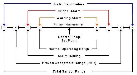
As seen in the center of the above figure, the control loop set point is the optimum point of control for the process (e.g. the optimum temperature and concentrations of reactants for a reaction). It is impossible to maintain the process at exactly this point, so there is a range of "normal" operation, inside which the process is still considered to be running in an acceptable way. The warning alarm would be triggered when the process goes outside of the limits of this range (lower than A or higher than B), allowing time for the process to be brought back under control. The critical alarm would then go off if the process goes beyond the alarm setting (lower than C or higher than D). This setting is determined by guard banding the process acceptable range (PAR) for uncertainty, seen in the figure by the fact that the alarm setting lies well inside the PAR. The spaces between E and C and between D and F are determined by the uncertainty. Lastly, this PAR must be inside the total range of the sensor that determines the instrument failure.
Alarms must be analyzed based on their priority: 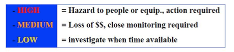
SAFETY STEPS TO HIGH RELIABILITY
A safe system involves many layers of responses when an incident occurs.

- The center of the ring is the basic process control system.
- The first layer of response is the alarm system which draws attention.
- The second layer is the Safety Interlock System which can stop/start the equipment.
- The third layer is the Relief system which leases pressure build-up in the sytem.
- The fourth layer is containment which prevents material from reaching workers, community, or the environment.
- The last layer to the ring is the emergency response system which involves evacuation, fire fighting, etc.
Worked out Example 1
A reagent recovery unit for a chemical process plant is being designed. The goal is to recover tin from a tin-plating waste stream through binary extraction with carbon tetrachloride. The equipment used in the process and P&ID are as follows:
- Carbon tetrachloride storage tank
- Mixing Vessel
- Pumps
- Heat Exchanger
- Associated piping

With knowledge of hazardous locations and risk hotspots, and safe design principles, analyze the flow diagram. Identify areas of risk and specific improvements that should be made to the process design before implementation begins. (note: no piping, valves, or controllers exist on the P&ID for the sake of clarity. Ignore these in your analysis) .
Areas of risk
Any piece of equipment could potentially become dangerous if the right situation were to arise. Each piece of equipment used in this process is no exception.
- Storage tank - These process units that are of secondary importance to the process goal, don’t draw as much attention from plant operators and engineers, and tend to receive less maintenance.
- Mixing Vessel - The potential for heat buildup due to heat of mixing and the kinetic energy of the spinning motor makes this vessel a risk hotspot. Improper control of temperature within the vessel or motor speed (especially during periods when the tank may be empty) can lead to equipment malfunction or even explosions
- Pumps and Heat exchangers - The energy stored through pressurization by the pumps and potentially high temperature solutions handled by the heat exchanger present the possibility for danger. Wherever energy is stored, danger is associated with its potential release.
- Associated piping - Corrosion or failure to maintain pipes and associated elements are the main cause of the malfunction leading to danger. Leaks or total failures can release reactive materials on other equipment causing corrosion or malfunction
Specific Improvements
This process could be improved and made safer in the following ways.
- Simplification of the piping used to connect the storage tank to the mixing vessel will reduce the risk of leaks and malfunctions due to piping complications.
- The addition of a emergency relief valve and temperature controlling/insulating element to the mixing vessel will greatly reduce the risk of equipment failure due to overheating or overpressureization due to heats of mixing or outside heating influences.
- Use a reactor with a rounded top, as this type can withstand much higher pressures.
- The substitution of carbon tetrachloride with a less hazardous solvent, if the specific solubility required to extract the tin still exists, like cyclohexane, isopropyl alcohol, or 1,1,1-trichloroethane reduces the risk of health complications due to exposure, and possible explosions.
A P&ID appears below for the production of a solution containing a pharmaceutically active compound. The reaction taking place in the CSTR is highly exothermic. After examining the P&ID for this part of the process, describe a possible alarm system.

Solution
The CSTR for the exothermic reaction is jacketed with a cooling water stream. An alarm should be in place to monitor the reactor temperature. A warning alarm can notify the operator that the temperature is too high and corrective action needs to be taken. A critical alarm should be in place to warn that the reactor is nearing runaway conditions and an immediate response is needed. If the necessary action is not taken, systematic shutdown of the reactor could occur. This would involve closing the valves, flooding the jacket with cooling water, and having the impeller on. Another possibility for an alarm, although we do not know how the products are being used specifically, is in a composition measurement of the product containing the pharmaceutically active compound. Depending on where this stream is going and how it is being used, too high a concentration could be dangerous if no other concentration-altering steps occur before the finished product goes out to consumers.
Actual Case
The bulletin below is taken for the US Chemical Safety and Hazard Invesitgation Board
Washington, DC, July 15, 2004 - The U.S. Chemical Safety and Hazard Investigation Board (CSB) today released a Safety Bulletin calling on chemical plant and refinery operators to exercise appropriate caution when performing work on piping and equipment that could contain hazardous materials.
The bulletin, set to be considered by the Board at a public meeting today, results from the CSB's investigation into a January 13, 2004, explosion and fire at the Huntsman Petrochemical facility in Port Neches, Texas, where two employees were seriously burned and significant damage occurred to nearby equipment. The explosion and fire occurred as workers attempted to purge a thousand-foot-long chemical process pipe in preparation for a cutting and welding operation.
Huntsman managers and workers were aware of the importance of completely removing hazardous material before cutting into the piping, and relevant warnings were contained in the company's written operating procedures. In this incident, workers first purged the piping with nitrogen to force out residual chemicals, including a hazardous mixture of peroxide and alcohol that reacts violently when heated. But unknown to the workers, the piping included a 300-foot-long section that was three feet lower than the rest of the piping, and despite the nitrogen purge, a significant amount of the hazardous mixture remained trapped. The next step in the operation was to use high-temperature steam to purge the piping of what workers believed would be a small amount of residual flammable hydrocarbon vapor. But the steam heated the peroxide that was trapped in the low section of piping. The peroxide then began to decompose, releasing heat and creating intense pressure. The pressure blew out a valve gasket and violently ruptured the pipe. Flammable vapors shot out of the openings and ignited into a large fireball, injuring plant workers.
After the accident, Huntsman found two drains in the low section of the pipe, which could have been used to remove the trapped liquid. Had Huntsman's procedures called for reviewing plant pipe drawings and physically walking the entire line within the work boundaries, the accident would likely have been avoided, CSB said.
Lessons Learned for this incident:
- Physically examine all piping and components between isolation devices such as valves, and be sure piping drawings are current
- Use the drawings to identify key components, such as low-point drains that can be used to remove dangerous chemicals
- Prepare a specific written procedure for removing hazardous material and consider the consequences of working on piping that is not completely purged.''
References
- AIChE (January 2006). Process Safety Beacon, CEP Magazine
- AIChE (March 2006). Process Safety Beacon, CEP Magazine
- AIChE (May 2006). Process Safety Beacon, CEP Magazine
- AIChE (November 2003). Process Safety Beacon, CEP Magazine
- AIChE (September 2006). Process Safety Beacon, CEP Magazine
- Gael D. Ulrich, Palligarnai T. Vasudevan (2006). Predesign With Safety in Mind, Univ. Of New Hampshire
- Georges A. Melhem, Peter Howell (2005). Designing Emergency Relief Systems for Runaway Reactions, CEP Magazine
- Joseph S. Alford, John Kindervater, Robert Stankovich (April 2005). Alarm Management for Regulated Industries, CEP Magazine
- U.S. Chemical Safety and Hazard Investigation Board, 15 July 2004. CSB News Release
- www.csb.gov/index.cfm?folder=news_releases&page=news&NEWS_ID=171
Contributors and Attributions
- Authors:Bradley Anderson, Aaron Bennick, Michael Salciccioli Stewards: Jocelyn Anleitner, Stephanie Combs, Diane Feldkamp, Heeral Sheth