
2.1: Verbal Modeling- process description, control specifications, and connections
- Page ID
- 22542

Authors: (September 8, 2006) Brian McQuillan, Crystal Miranda, Brandon Quigley, and John Zhang
Stewards: (September 5, 2007) Kevin Luchi, Mike Nappo, Matt Neff, Lisa Schauman
Introduction
Every process requires a great deal of planning in order to successfully accomplish the goals laid out by its designers and operators. In order to accomplish these goals, however, personnel that are not familiar with the design must fully understand the process and the functions of the control systems. Control systems consist of equipment (measuring devices, valves, etc.) and human intervention (plant operators and designers). Control systems are used to satisfy three basic needs of every process:
- Reduce the influence of external disturbances
- Promote the stability of the process
- Enhance the performance of the process
Verbal modeling is used for creating and also understanding a process control system. Verbal modeling consists of first receiving and then gathering information about the process. A step-by-step process is then used to describe the control systems used to satisfy constraints and objectives that have been outlined. In the following sections you will read what requirements are generally outlined for process control and the step-by-step method used to meet these requirements.
Prerequisite Information Regarding a Process
For the sake of this article it is assumed that a process has already been designed and that certain restraints and criteria are provided by either a customer, management, or the government. The goal of this section is to classify the types of criteria that are usually given. These criteria then become the conditions that the control systems employed must satisfy. In general, there will be five sets of criteria, often coming from different people and institutions. By gathering all of these criteria you will be able to describe the control system. If you do not have a complete list of these criteria you must research the process to determine these constraints before beginning the step-by-step process below.
Safety
The safe operation of a process is the biggest concern of those working in the plant and those that live in the surrounding community. The temperatures, pressures, and concentrations within the system should all fall within acceptable limits, and these limits can be dictated by either government agencies or company policy.
Production Objectives
The production objectives usually include both the amount and purity of the desired product. This criterion is generally set by the company or customer.
Environmental Regulations
These come in the form of restrictions on the temperature, concentration of chemicals, and flowrate of streams exiting a plant. State and federal laws, for instance, may dictate the exit temperature of a cooling water stream into a lake in order to prevent harm to aquatic wildlife.
Operational Constraints
Equipment found in the plant may have their own unique limitations, such as temperature or pressure that require proper control and monitoring. For instance, a thermocouple may be damaged at extremely high temperatures, thus the location of the thermocouple must be accounted for.
Economics
In general, a company will operate so that its profits are maximized. The process conditions that maximize these profits are determined by way of optimization. Many costs must be considered when optimizing process conditions. Some of these costs are fixed, or will not change with process variables (i.e. equipment costs) and others are variable, or do depend on process variables (i.e. energy costs). The overall process is usually limited by certain factors including availability of raw materials and market demand for the final product. Therefore, the economics of a process must be well understood before process changes are enforced.
Step-by-Step Method For Describing Controls and Their Purpose
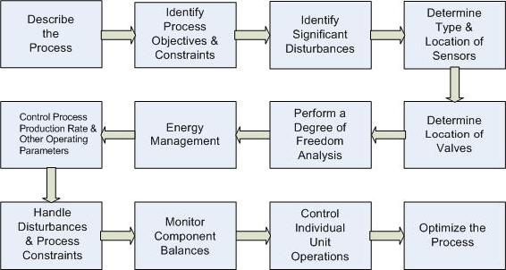
1.) Describe the Process
A brief description of the general process is needed while not dwelling on the details and calculations involved. The major steps of the process, as well as inputs and outputs of the process, should be stated. A simple diagram should be provided detailing the chemical process to help visualize the process.
2.) Identify Process Objectives and Constraints
The objectives and constraints of the process must be identified before process control actions can be performed.
The process objectives include the type, quantity, and quality of the product that is to be produced from the process. The economic objectives, such as the desired levels of raw material usage, costs of energy, costs of reactants, and price of products, should also be identified.
The process constraints include three different categories: operational, safety, and environmental limitations. Operational constraints refer to the limits of the equipment used in the process. For instance, a liquid storage tank can only hold a certain volume. Safety constraints describe the limits when the people or the equipment may be in danger. An example would be a pressure limitation on a reactor, which if exceeded, could result in an explosion. Environmental constraints limit how the process can affect the immediate surroundings. For example the amount of harmful chemicals that can be released before damage is done to nearby water supplies. All of these constraints should be mentioned to build a robust control system.
Careful reading of the information provided to you by the customer, management, and government is required in order to properly identify each constraint and objective. Often times, the process objectives will be very clearly laid out by the needs of the customer or management. Operational constraints, or the limitations of the equipment being used, must be researched for each piece of equipment used in the process. Generally, by satisfying the operational constraints a good portion of safety constraints are satisfied as well, but additional safety constraints may exist and must be investigated by researching company policy and governmental regulations. Environmental regulations also have to be researched through resources such as the EPA and Clean Air Act. Satisfying the economic aspect is largely determined by manipulating additional variables after all other constraints and objectives have been met.
3.) Identify Significant Disturbances
Disturbances, in the sense of process description, are defined as inputs or external conditions from the surrounding environment that have certain properties that cannot be controlled by the plant personnel. Examples of disturbances include ambient air temperature, feed temperature, feed flow rate, feed composition, steam pressure changes, and cooling water temperature changes. Disturbances can drastically affect the operation of a unit. A control system should be able to effectively handle all process disturbances. As such, all possible disturbances must be identified and these disturbances need to be accounted for by the development of contingency plans within the process.
4.) Determine Type and Location of Sensors
A proper design must ensure that adequate measurements of the system are obtained to monitor the process. To meet this goal, sensors must be chosen to accurately, reliably, and promptly measure system parameters. Such parameters include temperature, flow rate, composition, and pressure. Placement of sensors is important both in the usefulness of measurements as well as the cost of the system. Sensors should be placed such that the measured quantities are appropriate in addressing control objectives.
5.) Determine the Location of Control Valves
Valves must be placed in a location to control variables that impact the control objectives. For example, control of the temperature of a reactor could be obtained by placing a valve on either the stream of heating / cooling fluids or by placing a valve on the feed stream to the reactor. One must determine which streams should be manipulated to meet process objectives.
6.) Perform a Degree of Freedom Analysis
The degrees of freedom in a system are equal to the number of manipulated streams (determined in step 5) minus the number of control objectives and control restraints (determined in step 2). A degree of freedom analysis is used to determine if a system is being under- or over-specified by the process objectives. The degrees of freedom come from the number of knowns and unknowns that are specified within the system. If there are extra degrees of freedom present in a system, unused manipulated variables can be used to optimize the process. If there are negative degrees of freedom, a system is over-specified because more objectives and restraints exist than manipulated streams. In this case, all objectives cannot necessarily be met simultaneously and the least important objectives must be neglected. A system with zero degrees of freedom is fully specified. All objectives can be met, but there is no room for optimization.
7.) Energy Management
In any system with exothermic or endothermic reactions, distillation columns, or heat exchangers, energy management becomes a factor that must be accounted for. Heat must be removed from exothermic reactions in order to prevent reactor runaway, and heat must be supplied to endothermic reactions to ensure desired production rates. Strategies such as pre-heating feed streams with the excess heat from a product stream are helpful in maintaining efficient usage of energy, however, they also result in more complex processes that may require more intricate control systems.
8.) Control Process Production Rate and Other Operating Parameters
The production rate can be controlled by a variety of manipulated variables. One manipulated variable may be the feed rate. The plant feed rate can be changed and each subsequent unit can use its controls to accommodate this change, ultimately resulting in a change in the final production rate. Other manipulated variables may also include reactor conditions, such as temperature and pressure. Temperature and pressure affect reaction rates and can be used to alter the final production rate. It is important to choose the most suitable manipulated variable to control production rate.
In addition to the production rate, other control objectives must be effectively managed by manipulated variables. For example, temperature of an exothermic reactor may be controlled by the flow of a coolant stream passing over it in order to avoid dangerous high temperatures. The pressure of a reactor may be controlled by the flow of feed gas in order to comply with the pressure limitations of the vessel.
9.) Handle Disturbances and Process Constraints
The effects of disturbances should be minimized as much as possible, in order to maintain the system at desired conditions and meet all process objectives and constraints. Feedback or feedforward are specific control techniques and are common ways to overcome disturbances. A feedback control works by studying the downstream data and then altering the upstream process. The actions executed are reactive. Feedback can be viewed as an if-then statement: if a feed's temperature is detected to be lower than desired, then steam can be used to preheat the feed. Feedforward is a more proactive approach in that it adjusts a manipulated variable before the disturbance is felt in the process. Hence, if a sensor indicates low temperatures upstream of the feed, the feedforward control will counteract the effect of the cooler upstream temperatures by preheating the feed before the feed temperature is effected. Note that a disturbance must be detectable and measurable in order for the feedforward control to fix the anticipated disturbance before the system is effected.
Additionally, if constraints are reached during the process, controls should be implemented to avoid safety, operational, or environmental hazards. This can also be done with feedback and feedforward controls on manipulated variables.
10.) Monitor Component Balances
Every component within a process, whether it is inert or not, should be accounted for at every step of the system in order to prevent accumulation. This step is more crucial in processes that involve recycle streams. If such a stream is present, a purge stream is often necessary to remove unwanted components. In addition, component balances are used to monitor yield and conversion or reveal locations in the process where loss may be occurring. In order to monitor component balances, composition sensors are used.
11.) Control Individual Unit Operations
Most systems used today in industry employ the use of multiple unit operations. Each of these unit operations, however, needs to be fully controllable in the sense that it has a control system that can adjust manipulated variables in order to maintain other parameters. For instance, if an absorber is present, the system must be able to control the liquid solvent feed as some ratio to the gas feed. Another example is a crystallizer. The refrigeration load of the crystallizer must be controllable in order to control the temperature.
12.) Optimize the Process
In most cases, there will be certain aspects of a process that will not be dictated to a designer and can be changed to make the overall process more economical for the company. These are referred to as "unaccounted for" degrees of freedom and can be implemented as new control valves or adjustable controller setpoints.
Alternative Method of Verbal Modeling
This alternative method is also described in Peter Woolf's Recorded_Lectures Lecture 3. For purposes of this description, it is scaled down to a single unit process. However, this method can easily be applied to describe an entire system of unit processes.
1. Describe the process in words
Some of the important questions to answer before delving deeper into a model are:
- What are the components entering the system?
- How do they enter? Separately? Combined stream? What physical states are they in?
- What happens inside the unit process and what comes out at each exit point?
Remember to keep this part simple. There is no need to include chemical formulations or equations of any sort. Just lay out the basic flow of material.
2. Define the primary goal of the process
The primary goal should be simple. Often, it is to maintain a specific measured variable above a minimum or below a maximum. In this step, the only thing that needs to be determined is what the main goal is, and a few supporting details about why this is an important goal to achieve.
For example, a primary goal could be to minimize the concentration of Compound Y in orange juice because studies show Compound Y gives the juice a bad aftertaste.
3. Identify secondary processes that influence the primary goal
In a typical unit process, the primary goal will be directly influenced by one or two other aspects of the system. These can include temperature, pressure, inlet conditions, and more and can occur at various points in the process.
The goal of this step is to determine which of these other process variables will be most likely to influence the primary goal and to step down from there.
For example, the temperature of the orange juice mixer could have the greatest influence on production of Compound Y.
4. Identify safety and environmental risks
Next, you need to identify all of the points in the process that represent any type of risk. This will be important later in determining which system variables need to be monitored.
Step through your process and identify any points that pose a significant risk of the hazards shown in the following figure.
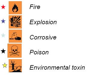
Examples include: Boilers represent fire and explosion risks. Any stream with a dangerous chemical can represent corrosive, poison, environmental, or all three risks.
5. Identify major costs associated with the process
How much something costs to produce is obviously a big deal in manufacturing. Identifying the largest sources of cost is critical in finding ways to reduce cost overall. Typical places to start identifying costs are at inlet streams (what is the cost of raw materials) and at any portion of the process where heat is added or removed.
It is important to include the high costs that can be associated with the risks identified in Step 4. Often the high cost of failure and risk exposure will determine what other seemingly costly steps must be taken to ensure the safety of the process.
6. Identify variables you can directly manipulate
The basics of the process have been laid out, and now it's important to determine what variables you can actually control. Typically, you only have direct control over the simplest of variables: switches and valves. Essentially, this just means that you cannot, in fact, choose a temperature for your system and implement it. What you can do, is control a valve or switch that activates heating or cooling to control the temperature.
During this step, you must decide where it is important to place these valves and/or switches. Use the information acquired previously about the primary goal and secondary effects to determine what variables are worth controlling. Remember that you don't need to put valves EVERYWHERE! Control valves are not costless and can also add unwanted complexity to your system. If you need to isolate equipment, you can install manual valves. Keep the control valves to the needed level.
7. Identify sources of variation
In order to write a control scheme, you need to know what values in your system will change and why. Some common causes of variation include:
- Environment: ambient temperature
- Other processes upstream or downstream: variable inlet conditions or outlet demand
- Economic forces: product worth, material costs
- Operators
Identifying what aspects of your process can be affected by these forces will allow you to assemble a more complete control scheme.
8. Describe your control system in words
Before you start trying to write everything out in computer code and mathematical equations, take the time to lay out your controls in words. This is much like preparing an outline before writing a paper. It can save you from many headaches later on.
One example of generic, simple syntax for verbal modeling is: Maintain [system variable] at specified level by adjusting [variable I can control].
The Barkel Method of Verbal Modeling
This method is an elaboration upon the steps outlined in Mr. Barry Barkel's lecture on September 29, 2009.
"If you design a system, you have the ethical responsibility to control it."
1) Understand the Process
Before you can control anything, you have to understand the process and how different parts of the system interact with each other. Make sure that the overall process is understood. This includes inputs and outputs as well as major steps, however specifics are not necessary. You should also be able to construct a diagram to help explain the process.
2) Identify Operating Parameters
Operating parameters can include temperature, pressure, flow, level, etc. Choose the parameters to manipulate in your system that will safely result in the desired output.
3) Identify hazardous conditions
Consider all possible dangerous aspects of your process when designing your system. This could include a chemical overheating or a vessel overflowing. It is imperative that you ensure the safety of your operators and being aware of all hazardous conditions can aid in this.
4) Identify measurables
The main three measureables addressed in this class are: temperature, pressure, and flow. However, there are many more measureables, some more common than others. Here are some more: pH, humidity, level, concentration, viscosity, conductivity, turbidity, redox/potential, electrical behavior, and flammability.
5) Identify points of measurement
It is important to place sensors in locations so that efficient and reliable measurements are taken of the system to monitor the process. For example, in a distillation column, temperature sensors will display different temperatures at different locations down the tower. The sensors must be positioned so that accurate readings of the system are given. Also, it is necessary to place sensors in an area of constant phase.
6) Measurement methods (thermo couple? choose for range)
After identifying what is to be measured and where it will be measured, you have to decide how it will be measured. For example, a thermocouple can be used to measure the temperature. When choosing the equipment, be sure to check that the conditions of use fall within the recommended range of operation for the equipment.
7) Select control methods
Decide whether to use feedback, feed-forward, cascade, or other types of control methods.
8) Select control system
A control system is a set of devices that will manipulate the actions of other devices in the system. A control system ranges from having an operator manually open and close a valve to running a system with feedback such as with PID controllers. Control systems can vary from relatively cheap to expensive. When picking a system, it would be most economic to choose the cheapest one that gets the job done. An example of a control system is a PIC, or programmable interface controller.
9) Select control limits
When choosing setpoints for controllers, you will also have to decide on a range that the values are allowed to fluctuate between before a corrective change is made. When selecting these limits, keep in mind that "equal" and "zero" do not exist due to the infinite number of decimals that electronics are now able to handle. So you must further define what "equal" means, when is it "close enough" to count as "equal" And when is the number small enough to count as "zero", is 0.1 or 0.01 or 0.0000000001 count as "zero"?
10) Define control logic
As every process is different, a customized code for each process must be written to tell the system what to do. For example, when a level control is a tank has reached a critically high point, the logic should spell out the necessary changes needed to bring the tank level back down. For example, this could be partially closing a valve upstream of the tank or partially opening a valve downstream of the tank.
11) Create redundancy system
In the real world, you must balance cost and efficiency/safety. On one hand, you don't want an out-of-control system if one control fails. But on the other hand, you can't afford to order two of everything. The critical point to keep in mind is to optimize the safety while minimizing the cost.
12) Define "fail-safe"
A fail safe is a set up in the control logic to ensure that in the event of a failure of a control method, the system will automatically reach a safe condition so that there is little to no harm done to other equipment or personnel.
13) Set lead/lag criteria
Valves and other equipment do not necessarily open/close or turn on/off at the exact instant a button is pressed or the control logic kicks in. There is often lag time associated with each controller. You must determine how long this lag time is so that you can take it into account.
14) Investigate effects of change before/after
Be sure to investigate effects of changing each controller. For example, what are the effects of closing/opening this valve?
15) Integrate all systems
Ensure that all systems are working together and that there are no holes in the system. Make sure that information does not fall through any cracks in the system.
[Note - we can use an example of the Barkel method - RZ]
Common Errors
1. Impossible direct manipulations e.g., Change the concentration of salt in a tank
2. Missing the forest for the trees e.g., Sacrificing product quality for tight level control on a tank
3. Excessive or insufficient control e.g., Control every variable because you can or ignore the possibility of significant disturbances
Worked out Example 1
PLEASE NOTE: ALL VALUES IN THE FOLLOWING PROBLEMS ARE FICTICIOUS BUT MEANT TO BE LOGICAL
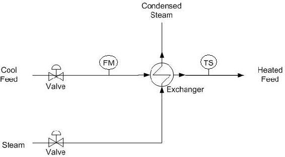
A heat exchanger uses steam to heat a stream of water from 50ºF to 80ºF. The water enters at a flow rate of 20 gallons per minute from a nearby lake. The process costs $65 per hour and yields a profit of $2 per gallon of product. The steam is provided by the plant and is 1000ºF, which is a temperature that the pipes can sustain. For safety reasons, the exchanger may only run for 12 consecutive hours and requires 4 hours to cool down. Using more than 10,000 gallons of water per hour would cause an environmental disturbance to the water source. The diagram is shown below. Verbally model this system.
== Solution ==
1.) Describe the Process
The purpose of the process is to heat an incoming stream of water from a temperature of 50ºF to a temperature of 80ºF. The main equipment involved is a shell-and-tube heat exchanger.
2.) Identify Process Objectives and Constraints
The product specification of the process is water at a flow of 20 gallons per minute and a temperature of 80ºF.
Economically, the process costs $65 per hour to operate. There are no costs for the raw materials, as the only inputs to the system are water and steam. The finished product produces a profit of $2 per gallon. The economic objective is to reduce process costs while producing sufficient product.
The operational constraints and safety concerns are due to the pipes. The pipes can only sustain a temperature of 1000ºF. Safety is a concern because attempting to heat the incoming water to a certain temperature may cause the heat exchanger to malfunction, leading to equipment damage and possible burn injuries to nearby personnel. The system may only operate for 12 consecutive hours, after which the system will need to be cooled down for 4 hours to avoid the aforementioned hazards. A simplified assumption is that there are no constraints on steam because it is provided by the plant and causes no safety issues. The only environmental constraints involve the incoming water stream. The incoming water is gathered from the nearby lake, and a stream of greater than 10000 gallons per hour would cause a disturbance in the equilibrium of the lake.
3.) Identify Significant Disturbances
Significant disturbances can be found in the ambient air temperature, variable flow rates of the feed, and the temperature of the steam.
4.) Determine the Type and Location of Sensors
A flow sensor (FM) is placed at the incoming water stream. A temperature sensor (TS) is located on the product water stream. A flow sensor is not needed for the steam stream for this problem because this value is not needed for control. A sensor could be placed here but the information is not needed for this problem.
5.) Determine the Location of Control Valves
A flow valve is placed at the entrance of the incoming water stream. A flow valve is placed at the entrance of the steam.
6.) Perform a Degree-of-Freedom Analysis
There are two manipulated variables: the flow of the water feed stream and the flow of the incoming steam. There are two control objectives: the flow of the feed stream, monitored by the flow sensor, and the temperature of the product, monitored by the temperature sensor. Therefore the system has zero degrees of freedom.
7.) Energy Management
The incoming steam is used to transfer heat to the cool water feed. The temperature sensor on the product stream determines the applicable setting on the steam flow valve.
8.) Control Process Production Rate and Other Operating Parameters
The process production rate is controlled by the flow valve on the entering water stream. The water temperature is controlled by the flow valve on the incoming steam.
9.) Handle Disturbances and Process Constraints
Changes in the ambient air temperature can be detected by the temperature sensor, and can be corrected by the flow valve on the incoming steam stream. Variable flow rates of the water feed stream can be detected by the flow sensor and compensated by adjustments on the flow valve on the water feed stream. Changes in the temperature of the steam can be detected by the temperature sensor. The flow valve on the steam stream can be adjusted to increase or decrease the flow of steam and subsequently the amount of heat exchanged.
10.) Monitor Component Balances
A vent is located on the heat exchanger to release excess steam from the system. Aside from that, any accumulation is unlikely and can be neglected.
11.) Control Individual Unit Operations
The outlet temperature of the product stream is controlled by the flow valve on the steam feed stream. The flow of the incoming water stream is controlled by the flow valve on the water feed stream.
12.) Optimize the Process
One might notice that the process is only using 1,200 gal/hr of water, well below the 10,000 gal/hr environmental constraint. If the profit of the process is linear with the flow-rate of water, then increasing the flow-rate of water will increase the profits for the company. (With the constraints specified, this is a Linear Programming optimization problem. The optimal setpoint falls on a boundary condition.) However, the flow-rate of water entering the system is already specified, which results in zero degrees of freedom. (Zero degrees of freedom implies there are no further control valves or setpoints.) Further investigation should be conducted to determine the reason for the flow-rate specification. When considering increasing the flow-rate of water into the system, one should also check that the other constraints are not violated.
Worked out Example 2
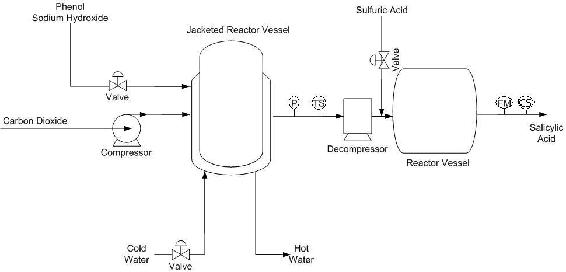
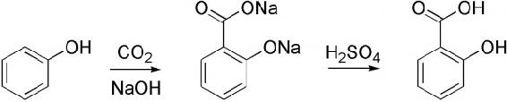
A process converts phenol into salicylic acid through a series of two reactors. Phenol and NaOH are fed in the liquid phase into the first reactor where it reacts with gaseous carbon dioxide that is pumped in. Assume constant fresh feed temperature and that the feed flow rate is within operational constraints. Management has dictated that salicylic acid production must be 200 moles per hour. Also, management would like the product stream to have a molar composition of 80% salicylic acid. Due to environmental concerns, a maximum flow rate of 10000 gallons per hour of cold water can be used to cool the first reaction chamber. The valve controlling the flow of cold water does not allow a flow rate in excess of 7500 gallons of water per hour. The salicylic acid product is used in another process to produce aspirin, which has a market value of $10 per mole. The first reactor can be operated at pressures up to 200 atm, while the second can be operated at pressures up to 10 atm. The first reaction is exothermic, while the second reaction is assumed to generate negligible heat. A diagram of this process is shown below, as well as the reaction scheme. Verbally model this system.
== Solution ==
1.) Describe the Process
The purpose of the process is to convert phenol into salicylic acid, the precursor for aspirin. First, the phenol is reacted with gaseous carbon dioxide (CO2) and sodium hydroxide (NaOH) under high pressure and temperature in the first reactor. The product of this reaction is then combined with sulfuric acid to form salicylic acid in the second reactor. The reaction scheme is shown above.
2.) Identify Process Objectives and Constraints
The process is expected to produce 200 moles per hour of salicylic acid. The product stream must contain at least 80% by moles of salicylic acid. The equipment used in the process dictates the operational limitations. The first reactor vessel can be operated up to a pressure of 200 atm, while the second reactor vessel has a 10 atm upward pressure limit. As such, pressures in excess of these limits must be avoided. Since the first reactor will generate a significant amount of heat, the heat must be removed to avoid damage to equipment and possible runaway reactions. Therefore, a heat exchanger (in the form of a reactor jacket in this case) with cool water should be included to decrease the temperature of the reactor. Economic concerns demand that phenol, sodium hydroxide, and sulfuric acid should not be used in extreme excess. The costs of these materials and the energy costs required to process them affect the overall profitability, so these compounds should not be wasted. Environmental regulations limit the use of water to cool the reactor at 10000 gallons per hour, however the valve constraints limits the amount of water to only 7500 gallons per hour.
3.) Identify Significant Disturbances
The amount of cold water available to cool the reactor can be considered a disturbance because it comes from a reservoir outside of our control. The ambient temperature is also a disturbance. If it drastically increases, the amount of cold water needed to cool the reactor would need to increase as well. Composition of the feed streams will be assumed to be constant in this example. Therefore, they are not considered disturbances.
4.) Determine the Type and Location of Sensors
A temperature sensor (TS) and pressure sensor (P) are located on the stream exiting the first reactor vessel. A flow meter (FM) is located on the product stream leaving the second reactor. A composition sensor (CS) will also be located on the product stream leaving the second reactor. The pressure drop can be controlled through the decompressor and thus is a control.
5.) Determine the Location of Control Valves
Control valves are located on the feed stream containing the phenol and sodium hydroxide, the incoming cold water to the first heat exchanger, and the sulfuric acid feed stream. There is also a pump located on the carbon dioxide stream that enters the reactor.
6.) Perform a Degree of Freedom Analysis
There are 3 valves, 1 pump, and 1 decompressor but 5 objectives. This results in zero degrees of freedom. The valve located on the sulfuric acid feed stream is meant to meet the composition constraint placed on the product stream leaving the second reactor. The valve located on the feed stream carrying the reactants is set to satisfy production requirements. The valve on the cold water stream is used to maintain reactor temperature, which satisfies an operational constraint. The pump is to ensure the correct pressure is achieved in the reactor, also satisfying an operational constraint. The decompresser is to maintain a pressure of less than 10 atm in the second reactor, thus satisfying another operational constraint.
7.) Energy Management
The heat from the exothermic reaction in the first reactor is transferred to the cold water stream. The hot water stream exiting the reactor vessel jacket could be used to heat streams on other processes. The second reactor is assumed to generate negligible heat during the reaction, thus any release of heat from the reactor will be considered safe to release into the environment surrounding the process.
8.) Control Process Production Rate and Other Operating Parameters
The production rate is measured by the flow sensor on the product stream and this signals the control valve on the feed stream through a feedback mechanism to change the production rate as necessary.
9.) Handle Disturbances and Process Constraints
If the temperature sensor on the reactor exit stream exceeds a certain level due to a diminished cold water supply, the feed stream valve would decrease the amount of reactants entering the reactor. The amount of feed would also be decreased if more than 7500 gallons per hour of cooling water were needed, as this is an operational constraint. If the pressure gauge controlling the pump begins to read higher than allowed pressures, the pump would decrease the flow of the carbon dioxide entering the reactor. Also, if the pressure gauge reads out a pressure that will be too high for the second reactor, the decompresser will be allowed to disperse more pressure. If ambient air temperature drastically increases, the temperature sensor would open the cold water valve allowing more cooling water to enter the reactor vessel jacket. If the composition of the product stream falls below 80 mole percent of salicylic acid, then the valve controlling the sulfuric acid feed would allow more sulfuric acid into the second reactor to increase the conversion of reactants.
10.) Monitor Component Balances
The composition sensor and flow meter on the product stream leaving the second reactor will account for every species to ensure that there is no accumulation or loss within the system.
11.) Control Individual Unit Operations
The first reactor vessel's pressure is fully controlled by the pressure gauge and pump system and its temperature is fully controlled by the temperature sensor which controls the reactant feed valve and the cool water valve. The second reactor's pressure is fully controlled by the same pressure gauge and the decompresser system, and its temperature will be highly dependent on the amount of cooling water used to cool the product exiting the first reactor.
12.) Optimize the Process
Since there are no unaccounted degrees of freedom, there are no valves to adjust in order to optimize the process. It should be noted, however, that if there was no constraint on the composition of the product stream, the sulfuric acid feed valve would have become an unaccounted for degree of freedom. If this had been the case, the valve could be adjusted to maximize the profit of the process. In order to maximize the profit, the benefits of having higher conversion and more product would have to be weighed against the increase costs of using more sulfuric acid feed.
Sage's Corner
An example of verbal modeling
http://www.youtube.com/watch?v=YTs_IWccnvw&feature=player_embedded
References
Luyben, William L., Tyreus, Bjorn D., and Luyben, Michael L. “Chapter 8: Eastman Process” in Plantwide Process Control, McGraw-Hill, New York, pp. 251-272.
Luyben, Michael L., Tyreus, Bjorn D., and Luyben, William L., "Plantwide Control Design Procedure" in AIChE Journal Dec. 1997, Vol. 43, No. 12 pp. 3161-3174.
Riggs, James B. and Karim, M. Nazmul. “Chapter 17: Multiunit Controller Design” in Chemical and Bio-Process Control, Ferret Publishing, pp. 491-504.
Stephanopoulos, George. Chemical Process Control: An Introduction to Theory and Practice, Prentice Hall, New Jersey, pp. 1-41.