
14.4: Summary- Summary on Control Architectures’ philosophies, advantages, and disadvantages.
- Page ID
- 22511

Summary on Control Architectures
A summary of the philosophies, advantages, and disadvantages of the different control architectures is shown below in Table 1.
| Philosophy | Advantages | Disadvantages | |
|---|---|---|---|
| Feedback | Control adjusts errors as they occur |
|
|
| Feed Forward | Control connects errors they occur |
|
|
| Ratio | Controls connects two flow to maintain a constant ratio |
|
|
| Cascade | Controls set points of sensors by controlling other sensors to integrate multiple information |
|
|
| Mixed | Control integrating combinations of control architectures |
|
|
Introduction
Liquid level and liquid pressure control are fundamental aspects of many control processes because of the reliance on the stability and convenience of liquid usage. The following article will introduce the main concepts behind liquid pressure control, liquid level control, examining the loop characteristics, response, tuning and limitations. Two models are included to illustrate the application of a liquid pressure control loop and a level control loop in idealized systems.
Pressure Control Basics
Like its counterparts of temperature, level and flow, pressure is one of the most common process variables. Pressure is a key process variable as it provides a critical condition for processes such as any chemical reaction, extrusion, boiling, distillation, air conditioning and vacuuming. Poor pressure control may likely lead to problems associated with quality, safety and productivity. For example, the presence of high-pressure conditions in a sealed vessel may result in an explosion and thus it is imperative that pressure be kept under good control within its safety limits.
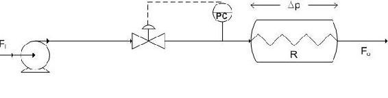
Liquid pressure control is one of the easier control loops in the sense that it is shares many of the same characteristics of a common flow loop. The aim of the liquid pressure loop is to control the pressure at the needed set point pressure by controlling the flow with changing process needs. Because dealing with a liquid, the flow present is that of an incompressible fluid and as a result the pressure changes very quickly leading to a fast-responding process with small dead time and capacitance. This process behaves as a fixed restriction where the change in pressure is a function of the flow through the process. Illustrated below is a diagram with liquid pressure control on the pipe leading to the process.
There are a few additional considerations for the aforementioned liquid pressure loop. Firstly the controller can be proportional plus integral (PI) or integral only (I-only) if Kc < 2 otherwise a proportional only (P-only) controller is to be used. This controller is tuned similarly to the flow controller. Another consideration is that process gain is not constant, a square-root extractor or the highest loop gain should be used in tuning the controller. This highest loop gain is employed to prevent the process loop from ever becoming unstable. Finally, this liquid pressure loop is noisy like its flow loop counterpart and as a result it is recommended that derivative action in the controller not be used.
If you wish to see the various issues associated with pressure controllers please refer to previous wiki articles.
Level Control Basics
Controlling the level of liquid in a tank is one of the most basic requirements for a chemical process to run effectively. Most chemical engineering processes require some sort of liquid to be held for usage, and the most convenient way of ensuring the proper amount of liquid is available is through level control. A specific example of a process that requires level control is seen around the world. Water towers must have a designated amount of water within them to ensure sufficient water pressure to surrounding neighborhoods and hence liquid level control (LLC) is used.
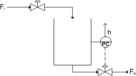
Fortunately Liquid level control is one of the easier control loops available. The systems are fairly simple, a sensor reads the level of liquid within a tank, which then is conveyed to the controller. Subsequently, the controller changes a valve to increase or decrease the flowrate into or out of the tank, depending on the required action and controlled valve placement. Below is a figure with LLC on the pipe leaving the tank.
The ease of LLC also lies in its large capacitance and nominal dead time. Usually hold-up times vary from 5-15 minutes. Problems may arise when signal noise becomes a factor, as it usually does with level controllers. Refer to previous wiki articles to the issues associated with level controllers(), however it is important to note that a measurement of weight instead of directly measuring level can be a effective way of eliminating noise.
P-only Controllers
Oftentimes using a P-only controller is the best way to ensure proper level control, in most cases only a small percent error will result, and it reduces problems associated with noise. P-only controllers should only be used when gain is very small and the tank has a large capacity. This will be the basis for the rest of the text.
A P-only controller works off the following principle of control:
\[\text{Output} =\text{Gain} \times \text{Error} + \text{Bias} \nonumber \]
The output directly effects a valve to control the flowrate into or out of the tank. Refer to the previous wiki articles to learn more about P-only control.
Level Measurement Noise
When controlling liquid levels in drums or vessels, an important aspect to consider is that there may be noise in the level measurement due to disturbances such surface turbulence, boiling of the liquid, or agitation. Due to the existence of this noise, using a derivative action controller may not be appropriate. However, if this type of controller action is used, there are various methods that may be employed to minimize the noise.
Method 1: Use a displacer in a stilling well
- Advantage: Filters high frequency noise due to turbulence in the tank
- Disadvantage: Bobbing level due to the low-frequency movement of tank liquid into the well resulting from the formation of a U-tube between tank and well
Method 2: Use an ultrasonic level measurement with electronic filtering of the signal
- Advantage: Works well when the level response period is much lower than the noise frequency
Method 3: Use a tank weighing method
In the this method, a loading device is placed beneath the tank supports to measure the mass of the tank. Output weight values are averaged by a transmitter which are then sent to a converter which outputs the corresponding level to the controller.
- Advantage: Effectively eliminates noise in the level measurement due to turbulence
Models
The following are Excel models of Pressure and Level control in simple systems. Proportional only control is used primarily for these models. Controller noise has been eliminated for sake of simplicity.
Liquid Pressure Control Model
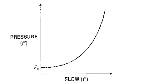
The model at hand illustrates both the feed backwards system of the liquid pressure in a pipline of a process and its process gain relationships. This liquid pressure control loop is regulated by the position of the valve on the pipeline leading to the process. A P-only control is used here to change the valve position resulting in the need response in attaining the set point value. The following are any assumptions made and the equations used in modeling this process. An assumption is made that the process behaves like a fixed restriction such as an orifice plate whose Dp is a function of flow through the process. Another assumption that should be made is that the valve responds linearly to the flow-rate through it. In determining the process gain the following equations where used.
\[P=\Delta p+P_{0} \nonumber \]
where \(P_0\) is the downstream pressure at zero flow
\[\Delta p=\frac{F^{2}}{R^{2}} \nonumber \]
where \(R\) is the process flow resistance. As a result we obtain:
\[P=\frac{F^{2}}{R^{2}}+P_{0} \nonumber \]
The gain of the process is then determined by the following expression:
\[K_{p}=\frac{d P}{d F}=\frac{2 F}{R^{2}} \nonumber \]
A model for the feed backwards system for liquid pressure control introduced in this article is very complicated and might possibly be out of the scope of our discussion. A possible alternative model would be very similar to the liquid level model presented below with the head in the tank determining the liquid pressure in the pipeline leaving the reactor.
Liquid Level Control Model
The following model represents a feed backward system of a liquid holding tank. The control loop is regulated by the exiting valve position on the pipe leaving the tank. A maximal flowrate out is assumed and the height of water in the tank does not have any effect on the flowrate out of the tank. This assumption can be made in tanks which are sufficiently wider than the pipe exiting operating with little liquid level change, as often is the case. Another assumption made is the linear response of the valve to flowrate out.
The pipe entering the tank is set by the user at a fixed flowrate. The P-only control is used to change the exiting valve position in order to cause the desired response to obtain the setpoint value. The P control follows the equation listed above and the bias is designated by the point at which the valve is open to allow a steady state to occur. Gain in Level control systems is usually low, however this can be changed by the user as well. The setpoint for the tank is determined by the user, as are the entering liquid flowrates and the maximal exiting flowrate.
The user can input a set point change in order to view the corresponding response in the controller.
Using the Liquid Level control Excel Model, what do you find when you change the level set point at a given point in time?
What happens if you change the gain to an large number?
Solution
When you change the level set point, you should notice a corresponding increase or decrease in the level as the P-control kicks in and beings to compensate for the error. The rate at which this set point is obtained is determined by the controller gain. At high controller gains the system responds extremely rapidly in an unreal fashion, this is why controller gain is usually small in large capacity tanks with flow control.
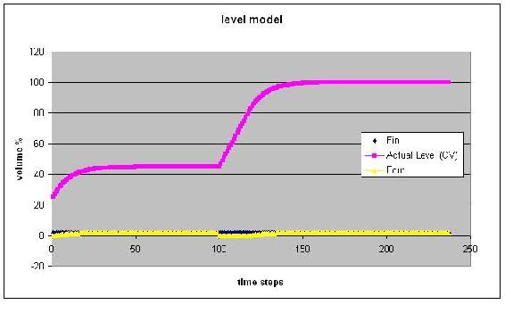
The above figure changes the setpoint to 100 @ t=100
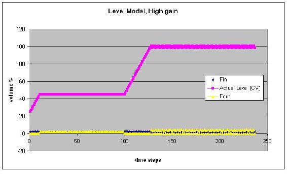
The above figure uses a very high controller gain. Note the unreal response.
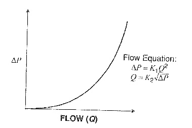
What is the primary difference between the model for the process gain of the pressure flow loop introduced earlier in the article and a typical head flow response curve?
Solution
The response of pressure to flow is shaped similarly to the response of the head flow device and as a result the rules that govern the liquid pressure process gain model are in essence the same for the head flow device response. The only difference between the two response curves is that whereas the pressure varies from Po to 100 per cent for the process gain curve for the pressure flow loop, the pressure varies from 0 to 100 percent for the head flow device.
Below is the response for the pressure loop followed by that of head flow device.
Multiple Choice Question 1
When should P-only controllers be used in Liquid Level control?
- Whenever, because it's really easy.
- Never because it is too simple.
- Sometimes, when the gain is small and the tank capacity is large.
- None of the above
Multiple Choice Question 2
Various methods may be used to minimize the noise in a level measurement when using which type of controller action:
- None, you can never minimize noise in a level measurement
- Integral
- Derivative
- PI-control