
3.9: Problems
- Page ID
- 82346
The tank shown in the figure is full of a liquid and initially contains \(1000 \ \mathrm{lbm}\) of liquid. (The density of the liquid is \(60 \ \mathrm{lbm} / \mathrm{ft}^{3}\) ). The sides and base are rigid but the top wall of the tank can float up and down without leakage. The tank has one inlet and one outlet as shown in the figure. The following information is known about the mass flow rate at the inlet and the outlet: \[\begin{aligned} &\dot{m}_{1}=\left\{\begin{array}{l} \left(3 \ \frac{\mathrm{lbm}}{\mathrm{min}^{2}}\right) t \text { when } 0 \leq t \leq 6 \mathrm{~min} \\ 18 \ \mathrm{lbm} / \mathrm{min} \text { when } t>6 \mathrm{~min} \end{array}\right. \\ &\dot{m}_{2}=(18 \ \mathrm{lbm} / \mathrm{min})\left(1-e^{-t /(3 \mathrm{~min})}\right) \end{aligned} \nonumber \]
.png?revision=1&size=bestfit&width=511&height=311)
Figure \(\PageIndex{1}\): System consisting of the contents of a tank with a floating lid, one inlet and one outlet.
(a) Using an open system as shown in the figure that corresponds to the volume of liquid inside the tank, answer the following questions:
- Calculate and graph the rate of change of the mass inside the tank at one-minute intervals for \(0 \leq t \leq 20 \mathrm{~min}\).
- Calculate and graph the amount of mass inside the tank at one-minute intervals for \(0 \leq t \leq 20 \mathrm{~min}\).
- Calculate the net change in the volume of the system for the 20-minute time interval.
- Is the system at steady-state during this 20-minute period? Would it ever reach a steady-state condition at any time?
(b) How would your answers to part (a) change if you used an open system that included the walls of the tank inside your system? A qualitative discussion is acceptable.
A system of four tanks is connected as shown in the figure below.
.png?revision=1&size=bestfit&width=882&height=502)
Figure \(\PageIndex{2}\): System consisting of 4 tanks, interconnected by 9 pipes.
The flow net formed by the tanks and their piping operates at steady-state conditions. The known mass flow rates are indicated in the table below:
| Pipe Number | \(\mathrm{kg} / \mathrm{s}\) |
|---|---|
| 1 | 50 |
| 2 | 30 |
| 3 | |
| 4 | 60 |
| 5 | |
| 6 | |
| 7 | 40 |
| 8 | |
| 9 | 80 |
(a) Determine the unknown mass flow rates, in \(\mathrm{kg} / \mathrm{s}\). Clearly show the system(s) you use to develop the necessary equations.
(b) The degree of freedom of a problem is the number of variables that must be specified before the remaining variables can be calculated. Assuming that mass flow rates are the only variables in this problem and that conservation of mass is the only pertinent physical law required for solving it, how many degrees of freedom does this problem have? Or, looking at it another way, how many of the nine mass flow rates must be specified before the remaining mass flow rates can be determined uniquely? The specified variables are sometimes referred to as the design variables and the unknown variables to be determined are called the state variables.
The air scoop on the hood of a car is sketched in the figure, along with the velocity profile of the air immediately upstream of the scoop inlet. Air flows directly into the scoop at 1 and then exits the scoop at 2 at an angle \(\theta=30^{\circ}\). The scoop has a rectangular cross section with a uniform depth \(d=25 \mathrm{~cm}\) into the screen. At the inlet \(H=5 \mathrm{~cm}\) and at the outlet \(2 H=10 \mathrm{~cm}\). The velocity profile shows how the velocity \(u\) varies with vertical position \(y\). For purposes of analysis, \(U_{0}=27 \mathrm{~m} / \mathrm{s}\) and \(\delta=2.5 \mathrm{~cm}\). Assume air behaves as an incompressible substance. Assume steady-state operation.
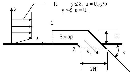
Figure \(\PageIndex{3}\): Profile view of the air scoop with measurements.
(a) Calculate the volumetric flow rate of air into the scoop, in \(\mathrm{m}^{3} / \mathrm{s}\).
(b) Determine the volumetric flow rate of air leaving the scoop at 2, in \(\mathrm{m}^{3} / \mathrm{s}\).
(c) Determine the magnitude of the average velocity \(V_{2}\) at the scoop outlet, in \(\mathrm{m} / \mathrm{s}\).
The cross-sectional area of a rectangular duct is divided into 16 equal rectangular areas, as shown in the figure. The axial fluid velocity is measured at the center of each area and is reported in the figure in feet per second. Assume that atmospheric air flows in the duct.
.png?revision=1)
Figure \(\PageIndex{4}\): Divisions of the cross-section of a rectangular air duct.
(a) Estimate the volume flow rate in \(\mathrm{ft}^{3} / \mathrm{s} \ \text{(cfs)}\) and \(\mathrm{ft}^{3} / \mathrm{min}(\mathrm{cfm})\) and the average axial velocity in \(\mathrm{ft} / \mathrm{s}\).
(b) Assume that the rectangular duct is the inlet section of a transition fitting that connects rectangular to circular sheet metal ducting. If the outlet circular duct has a diameter of 12 inches, what is the volume flow rate and average velocity in the circular duct?
(Adapted from White, Fluid Mechanics, 4th ed., WCB/McGraw-Hill.)
When a fluid (liquid or gas) flows through a surface, the velocity may vary with position. The equation or graph that describes this variation is known as the velocity profile. A thin layer of liquid, draining from an inclined plane as shown in the figure, will have a laminar velocity profile described by the following equation:
\[u = U_0 \left[ 2 \left( \frac{y}{h} \right) - \left(\frac{y}{h} \right) ^{2} \right] = \left(2 \frac{U_0}{h} \right) y - \left( \frac{U_0}{h^2} \right) y^{2}, \nonumber \] where \(U_{0}\) is the surface velocity, i.e. velocity of the water at the surface of the layer, \(u\) is the velocity of the water at any \(y\)-position in the layer, and \(h\) is the thickness of the layer. A graph of this velocity profile is shown in the figure.
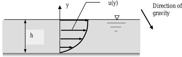
Figure \(\PageIndex{5}\): Velocity profile of a layer of liquid flowing down an inclined plane.
(a) If the plane has width \(b\) into the screen, develop an expression for the volumetric flow rate in the film in terms of \(h\), \(U_0\), and \(b\). [Hint: Use a differential area element \(dA=b \ dy\) and integrate from \(y=0\) to \(y=h\).
(b) Calculate the mass flow rate of liquid down the plane, in \(\mathrm{kg} / \mathrm{s}\), if the liquid is SAE 10W motor oil with a specific gravity of \(0.87\) and \(b=0.3 \mathrm{~m},\) \(h=5 \mathrm{~mm}\), and \(U_{0}=0.2 \mathrm{~m} / \mathrm{s}\).
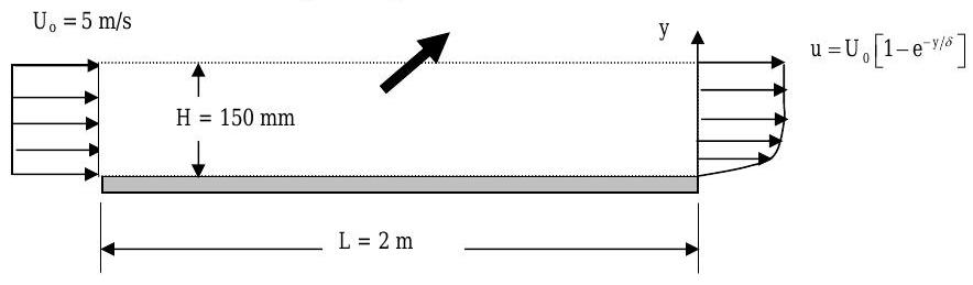
Air flows over a flat plate and the flat plate produces a region of retarded flow near the plate surface. In this region, known as the boundary layer, the fluid velocity \(u=0\) at the plate surface \((y=0)\) and \(u\) approaches \(U_{o}\), the free-stream velocity, far away from the wall \((y>>\delta)\). Measurements reveal that \(u / U_{o}=0.99\) when \(y=23 \mathrm{~mm}\). The plate has a width (into the paper) \(w=10 \mathrm{~m}\).
Determine (a) the value of \(\delta\) using the given velocity profile, (b) the volumetric flow rate of air represented by the large black arrow, i.e. flow across the dashed surface, and (c) the average velocity normal to the dashed surface.
.jpg?revision=1)
Figure \(\PageIndex{6}\): Air velocities at the edges of a flat plate.
An air supply system has an exhaust tee as shown in the figure. The air enters at Inlet 1 with a density of \(0.075 \ \mathrm{lbm} / \mathrm{ft}^{3}\) and a velocity of \(15 \ \mathrm{ft} / \mathrm{s}\). The mass flow rates at Outlet 2 and Outlet 3 are equal; however, the outlet velocities are different. The cross-sectional area (shown by a dashed line) is \(2.0 \ \mathrm{ft}^{2}\) for Inlet 1 , \(2.3 \ \mathrm{ft}^{2}\) for Outlet 2, and \(2.3 \ \mathrm{ft}^{2}\) for Outlet 3.
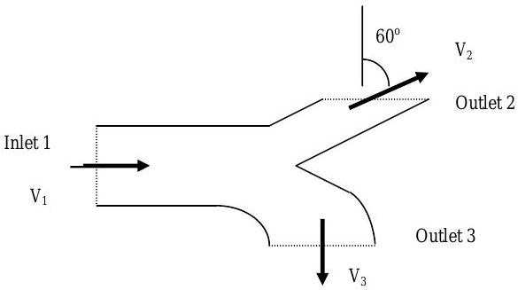
Figure \(\PageIndex{7}\): Profile view of exhaust tee, showing the directions in which air enters or exits through each opening.
For purposes of analysis, you may assume that the air is incompressible and the tee operates at steady-state conditions. All flows may be assumed as one-dimensional. Except for Outlet 2, the average velocity crossing the boundary is perpendicular to the flow boundary. At Outlet 2, the flow leaves with an angle of \(60^{\circ}\) as shown on the figure.
Determine:
(a) the mass flow rate at each inlet and outlet, in \(\mathrm{lbm} / \mathrm{min}\).
(b) the average velocity \(V_{2}\) at Outlet 2 and \(V_{3}\) at Outlet 3, in \(\mathrm{ft} / \mathrm{s}\).
(Adapted from Potter & Wiggert, Mechanics of Fluids, 2nd ed., Prentice Hall)
Water flows steadily through a radial outflow turbine as shown in the figure. The water enters the turbine flowing parallel to the axis-of-rotation of the turbine with a velocity of \(15 \mathrm{~m} / \mathrm{s}\) and leaves the turbine flowing radially outward with a velocity \(V_2\) at an angle \(\theta\) as shown in the figure. The exit angle depends on the operating conditions of the turbine.
.jpg?revision=1)
Figure \(\PageIndex{8}\): Side and end views of the radial outflow turbine.
Assume that water is incompressible with a density of \(1000 \mathrm{~kg} / \mathrm{m} 3\) and recognize (learn) that the phrase "flows steadily" implies that the turbine operates at steady-state conditions.
(a) Determine the mass flow rate at the turbine inlet, in \(\mathrm{kg} / \mathrm{s}\).
(b) Determine the volumetric flow rate at the turbine inlet, in \(\mathrm{m}^3 / \mathrm{s}\).
(c) Determine the average velocity \(V_2\) of the water leaving the turbine if \(\theta=0 ^{\circ}\), \(30 ^{\circ}\), and \(60 ^{\circ}\).
A hydraulic pump operates the elevators in Moench Hall by forcing fluid into a vertical cylinder with a piston that supports the elevator. As fluid is forced into the cylinder, the piston moves and pushes the elevator between floors. The hydraulic fluid is supplied to the pump from a small reservoir as shown in the figure. The elevator travels up and down at the rate of \(0.6 \mathrm{~m} / \mathrm{s}\) and travels a total distance of \(6.0\) meters. The diameter of the lower face of the cylindrical piston is \(10 \mathrm{~cm}\). The oil reservoir is a steel tank vented to the atmosphere, is \(0.6\) \(\mathrm{m}\) tall and has a \(1.0 \mathrm{~m} \times 1.0 \mathrm{~m}\) footprint (length \(\times\) width). With the elevator at its lowest elevation, the oil reservoir is \(2 / 3\) full. For analysis purposes, you may assume that the hydraulic oil is incompressible.
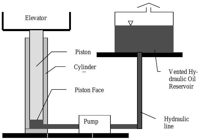
Figure \(\PageIndex{9}\): Setup of the hydraulic oil reservoir used to raise an elevator.
(a) Starting with the conservation of mass equation and an open system of your choice, determine
- the required volumetric flow rate out of the pump in \(\mathrm{m}^{3 / s}\) and gallons per minute \((\mathrm{gpm})\) to raise the elevator at the indicated velocity.
- the velocity of the oil at the pump outlet if the hydraulic lines have a diameter of \(0.020 \mathrm{~m}\).
[Hint: Try a one-inlet, deforming open system that contains all of the oil downstream of the pump. The system inlet corresponds with the pump outlet and the moving boundary is the lower face of the piston.]
(b) Starting with the conservation of mass equation and an open system of your choice, determine the rate of change, in \(\mathrm{m} / \mathrm{s}\), of the oil level in the reservoir when the elevator is going up. [Hint: Try a one-inlet open system with changing volume.]
(c) Using a closed system consisting of all the oil in the cylinder, lines, pump, and reservoir, determine the rate of change, in \(\mathrm{cm} / \mathrm{s}\), of the oil level in the reservoir when the elevator is going up.
(d) Using any approach that clearly demonstrates its connection to the conservation of mass principle, determine the oil level in the reservoir when the elevator is at its highest elevation.
Gasoline ( S.G. \(=0.7\) ) drains by gravity from the upper tank to the lower tank through a connecting pipe. The liquid depth in the upper tank is decreasing at the rate of \(0.333 \mathrm{~m} / \mathrm{min}\). The area of the base of the upper tank is Aupper \(=9 \mathrm{~m}^{2}\) and the area of the base of the lower tank is \(A_{\text {lower }}=50 \mathrm{~m}^{2}\). The walls of both tanks are vertical as shown in the figure. The pipe connecting the tanks is 50 meters long and has a diameter of \(0.10 \mathrm{~m}\).
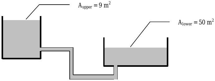
Figure \(\PageIndex{10}\): Setup of two pipe-connected tanks, one situated higher than the other.
(a) Starting with the rate form of the conservation of mass and an appropriate open system, determine the volumetric flow rate and the speed of the fluid in the connecting pipe connecting, in \(\mathrm{m}^{3} / \mathrm{min}\) and \(\mathrm{m} / \mathrm{s}\), respectively.
(b) Starting with the rate form of the conservation of mass and an appropriate open system, determine the rate at which the depth of oil in the lower tank changes, in \(\mathrm{m} / \mathrm{min}\). Clearly indicate whether the level is increasing or decreasing.
(c) Repeat Part (b), but this time use an appropriate closed system, e.g. all of the oil in both tanks and in the connecting pipe.
A vertical cylindrical tank has a diameter \(D=5\) meters, is 10 meters deep, and contains water. The tank drains from the bottom of the tank through an opening with a diameter of 5 centimeters. The volumetric flow rate of the water out of the tank is proportional to the depth of the water in the tank \(h\) and varies according to the equation \(\dot{V\kern-0.8em\raise0.3ex-} = \sqrt{ \left( 18.0 \mathrm{~m}^{5} / \mathrm{s}^{2} \right) h}\). If the depth of the water is initially 6 meters, determine how long it will take the tank to drain until the water depth decreases to 2 meters. If necessary, assume that water is an incompressible substance with a density of \(1000 \mathrm{~kg} / \mathrm{m}^{3}\).
An automobile tire having a volume of \(3 \ \mathrm{ft}^{3}\) contains air at an absolute pressure of \(32 \ \text{psi} \ ( \text{lbf} / \mathrm{in}^{2} ) \) and a temperature of \(70^{\circ} \mathrm{F} \ \left( 530^{\circ} \mathrm{R} \right)\). Assume that air can be modeled as an ideal gas under these conditions. [If Fahrenheit ( \({ }^{\circ}\) \text{F}) and Rankine \(\left({ }^{\circ} \mathrm{R}\right)\) temperatures are new or confusing, check out the unit conversion page and possibly your physics book or a dictionary.]
(a) Determine the mass of the air inside the tire, in \(\text{lbm}\).
(b) If the tire sits overnight and the temperature drops to \(32^{\circ} \mathrm{F} \ \left( 492 ^{\circ} \mathrm{R}\right) \), determine the new pressure in the tire. Assume no air leaks out of the tire and the volume of the tire remains constant.
(Just for fun. Not required: How much would the tire footprint change?)
The breathing rate of an adult is approximately 12 breaths per minute and with each breath approximately \(0.18 \mathrm{~mol}\) (not \(\mathrm{kmol}\) ) of gas is exhaled. The table below shows the molar composition (mole fractions) of the gases in the gas mixture exhaled.
| Species | Mole Percent | |
|---|---|---|
| Oxygen | \(\mathrm{O}_{2}\) | \(15.1 \%\) |
| Carbon dioxide | \(\mathrm{CO}_{2}\) | \(3.7 \%\) |
| Nitrogen | \(\mathrm{N}_{2}\) | \(75.0 \%\) |
| Water vapor | \(\mathrm{H}_{2} \mathrm{O}\) | \(6.2 \%\) |
(a) Determine the composition of the gas mixture on a mass basis, i.e. find the mass fraction of each mixture component. [Hint: Set up a table as shown in the text and work across from known mole fractions to mass fractions.]
(b) Determine mass of exhaled gases, in grams.
(c) Determine the apparent molar mass for the gases, in \(\text{g} / \text{mol}\) or \(\mathrm{kg} / \mathrm{kmol}\).
(d) Calculate the volume of gas exhaled, in \(\mathrm{m}^{3}\) and in \(\mathrm{cm}^{3}\), if the gas exhaled has a temperature of \(37^{\circ} \mathrm{C} \ (310 \mathrm{~K})\) and a pressure of \(99 \ \mathrm{kPa}\). Assume that the exhaled gas may be modeled as an ideal gas.
The composition of a gaseous fuel has been experimentally determined as shown in the table. The fuel is flowing at a rate of \(1000 \ \mathrm{ft}^{3} / \mathrm{min}\) at a pressure of \(200 \ \text{psi}\) and \(60^{\circ} \mathrm{F}\).
| Compound | Mole % | |
|---|---|---|
| Methane | \(\mathrm{CH}_{4}\) | \(65 \%\) |
| Ethane | \(\mathrm{C}_{2} \mathrm{H}_{6}\) | \(25 \%\) |
| Carbon Dioxide | \(\mathrm{CO}_{2}\) | \(5 \%\) |
| Nitrogen | \(\mathrm{N}_{2}\) | \(5 \%\) |
Determine the
(a) composition of the fuel on a mass basis,
(b) apparent molar mass of the fuel, and
(c) the mass flow rate of the fuel at the conditions indicated assuming the fuel behaves like an ideal gas, in \(\mathrm{lbm} / \mathrm{min} .\)
A mixture containing \(55 \%\) benzene (B) and \(45 \%\) toluene (T) by mass is fed into a distillation column. The overhead stream is \(95 \%\) benzene by mass. The feed rate is \(3000 \mathrm{~kg} / \mathrm{h}\). Assume steady-state operation. Determine the unknown flow rates and compositions.
.png?revision=1)
Figure \(\PageIndex{11}\): The streams of material entering and leaving a distillation column.
| Stream | Mass Flow Rate | Composition | ||
|---|---|---|---|---|
| Benzene | Toluene | |||
| 1 | Feed | \(3000 \mathrm{~kg} / \mathrm{h}\) | \(55 \%\) | \(45 \%\) |
| 2 | Overhead | \(95 \%\) | ||
| 3 | Bottom | \(2130 \mathrm{~kg} / \mathrm{h}\) | ||
In a process producing jam, crushed fruit containing \(14 \%\) fruit solids by weight is mixed in a mixer with a sugar solution and pectin. The resultant mixture is then evaporated in a kettle to produce a jam. The known flow rates and compositions are shown in the table.
Determine the unknown flow rates and compositions, i.e. complete the table below. Assume steady-state operation.
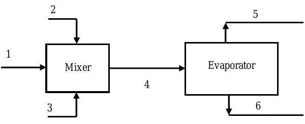
Figure \(\PageIndex{12}\): Streams of material entering and leaving a system consisting of a mixer and an evaporator.
| Stream | Stream Contents | Mass Flow Rates | Composition (Mass %) | |||
|---|---|---|---|---|---|---|
| Fruit Solids | Sugar | Pectin | Water | |||
| 1 | Crushed fruit | \(1000 \ \text{kg} / \text{h}\) | \(14 \%\) | \(\cdots\) | \(\cdots\) | \(86 \%\) |
| 2 | Sugar solution | \(1.3 \dot{m}_1\) | \(\cdots\) | \(94 \ %\) | \(\cdots\) | \(6 \%\) |
| 3 | Pectin | \(0.0025 \dot{m}_1\) | \(\cdots\) | \(\cdots\) | \(100 \%\) | \(\cdots\) |
| 4 | Mixture | |||||
| 5 | Water | \(\cdots\) | \(\cdots\) | \(\cdots\) | \(100 \%\) | |
| 6 | Jam | \(33 \%\) | ||||
A solid material containing \(15.0 \%\) moisture by weight is dried in a steady-state process so that it contains \(7.0 \%\) water by weight. The moisture is removed by blowing fresh warm air mixed with recycled air over the solid in the dryer. Atmospheric air (moist air) used in this process can be modeled as a two-part mixture of dry air and water vapor (moisture). The known flow rates and compositions are shown in the table.
.jpg?revision=1)
Figure \(\PageIndex{13}\): Streams of material entering and leaving the system of a dryer.
| Stream | Stream Contents | Mass Flow Rate | Composition (Mass %) | ||
|---|---|---|---|---|---|
| Water | Dry Air | Solid | |||
| 1 | Moist solid | \(100 \ \text{kg} / \text{h}\) | \(15.0\) | \(\cdots\) | |
| 2 | Fresh warm air | \(0.99\) | \(\cdots\) | ||
| 3 | Dry solid | \(7.0\) | \(\cdots\) | ||
| 4 | Moist air out | \(9.09\) | \(\cdots\) | ||
| 5 | Moist air recycled | \(9.09\) | \(\cdots\) | ||
| 6 | Mixed air | \(2.91\) | |||
(a) Determine the unknown mass flow rates and compositions on a mass basis.
(b) The fresh warm air is supplied to the dryer at \(50^{\circ} \mathrm{C}\) and \(120 \ \mathrm{kPa}\). Assuming as a first approximation that the air can be modeled as an ideal gas with a molar mass \(M=28.97 \mathrm{~kg} / \mathrm{kmol}\), calculate the volumetric flow rate of the fresh warm air in \(\mathrm{m}^{3} / \mathrm{min}\). [Hint: Calculate the density of the air first and then the volumetric flow rate.]
Carbon disulfide \(\left(\mathrm{CS}_{2}\right)\) is to be recovered from a gas containing \(15.0 \% \mathrm{CS}_{2}, 17.8\) \(\% \mathrm{O}_{2}\), and \(67.2 \% \mathrm{~N}_{2}\). The gas is fed to a continuous absorption tower that operates at steady-state conditions. Inside the tower the feed gas contacts liquid benzene, which absorbs \(\mathrm{CS}_{2}\) but not \(\mathrm{O}_{2}\) or \(\mathrm{N}_{2}\). The liquid benzene is fed to the column in a \(2: 1\) mole ratio to the feed gas. Some of the benzene entering as liquid evaporates and mixes with other gases and leaves the top of the tower in the product gas. No chemical reactions occur inside the tower. (Adapted from Elementary Principles of Chemical Processes by Felder and Rousseau.)
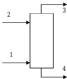
Figure \(\PageIndex{14}\): Inlets and outlets for a continuous absorption tower.
| Inlets/Outlets | \( \dot{n}_{i} \ ( \text{kmol} / \text{min} ) \) | Composition (mole %) | |||
|---|---|---|---|---|---|
| \(\text{CS}_2\) | Benzene | \(\text{N}_2\) | \(\text{O}_2\) | ||
| 1: Feed gas | \(100\) | \(15.0\) | \(\cdots\) | \(67.2\) | \(17.8\) |
| 2: Feed liquid | \(\cdots\) | \(100\) | \(\cdots\) | \(\cdots\) | |
| 3: Product gas | \(2.0\) | \(2.0\) | |||
| 4: Product liquid | |||||
(a) Find the unknown mole fractions and molar flow rates indicated in the table.
(b) Find the fraction of the \(\text{CS}_2\) fed to the column that is carried out in the product liquid.
(c) Find the fraction of benzene fed to the column that is carried out in the product gas.
To make strawberry jam, a two-stage process is used as shown in the figure. First, crushed strawberries and sugar are mixed in a \(45: 55\) ratio by mass. Then the mixture is heated to evaporate water until the residue contains one-third water by mass. Strawberries contain about \(15 \%\) solids (S) and \(85 \%\) water (W) by mass.
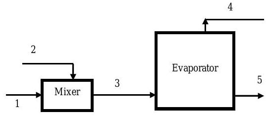
Figure \(\PageIndex{15}\): Process stages and inlet/outlet streams in the process of jam making.
Assume steady-state operation and provide the missing information in the table below:
| Stream | Mass Flow Rate \((\mathrm{lbm} / \mathrm{h})\) | Composition (Weight Percent) | |||
|---|---|---|---|---|---|
| Strawberry Solids | Water | Sugar | |||
| 1 | Strawberries | \(4500\) | \(15 \%\) | \(85 \%\) | \(\cdots\) |
| 2 | Sugar | \(5500\) | \(\cdots\) | \(\cdots\) | \(100 \%\) |
| 3 | Evaporator Feed | ||||
| 4 | Water | \(\cdots\) | \(100 \%\) | \(\cdots\) | |
| 5 | Strawberry Jam | \(33 \%\) | |||
[Adapted from Felder & Rousseau]
In the production of a bean oil, beans containing \(10 \%\) oil and \(90 \%\) solids (by weight) are ground and fed to a stirred tank extractor where they are suspended in liquid \(n\)-hexane. Essentially all of the oil in the beans is extracted into the hexane in the extractor.
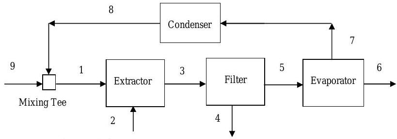
Figure \(\PageIndex{16}\): Process stages and inlet/outlet streams in the process of bean oil production.
The effluent from the extractor passes through a filter as shown in the figure. The filter cake contains \(75 \%\) by weight bean solids and the balance is bean oil and hexane. The ratio of the mass of bean oil to the mass of hexane in the filter cake is the same as it was in the extractor effluent, i.e. \(mf_{4, \text { oil}} / mf_{4, \text { hexane}}=m f_{3, \text { oil}} / m f_{3, \text { hexane}}\).
The filter cake is discarded, and the liquid filtrate is fed to a vacuum evaporator, in which the hexane is vaporized and thereby separated from the oil. The hexane vapor is subsequently condensed and recycled to the extractor. Assume the process operates at steady-state conditions.
Determine the unknown information in the table.
Stream |
Mass Flow Rate \(( \text{kg} / \text{h}) \) | Weight % | |||
|---|---|---|---|---|---|
| Hexane | Solids | Oil | |||
| 1 | Hexane (Recycled) | \(3000\) | \(100\) | \(\cdots\) | \(\cdots\) |
| 2 | Beans | \(1000\) | \(\cdots\) | \(90\) | \(10\) |
| 3 | Effluent | ||||
| 4 | Filter Cake | \(75\) | |||
| 5 | Liquid Filtrate | \(\cdots\) | \(\cdots\) | ||
| 6 | Oil | \(\cdots\) | \(\cdots\) | \(100\) | |
| 7 | Hexane (Vapor) | \(100\) | \(\cdots\) | \(\cdots\) | |
| 8 | Hexane (Liquid) | \(100\) | \(\cdots\) | \(\cdots\) | |
| 9 | Hexane (Fresh Liquid) | \(100\) | \(\cdots\) | \(\cdots\) | |
An elevated water-storage tank is fed from a very large reservoir and supplies water to a community as shown in the figure. The level \(H\) of the water in the reservoir remains constant at \(400 \ \mathrm{ft}\) under all conditions and the level \(h\) of water in the tank changes with time. The base of the water tank has an area of \(750 \ \mathrm{ft}^{2}\) and the tank is a vertical cylinder. The following volumetric flow rates are known:
Into the tank from the reservoir: \(\dot{\(V\kern-0.8em\raise0.3ex-\)}_{reservoir} = K_{res} \sqrt{H-h} = \left( 9.0 \ \mathrm{ft}^{2.5} / \mathrm{min}\right) \sqrt{H-h}\)
Out of the tank to the community: \(\quad \dot{\(V\kern-0.8em\raise0.3ex-\)}_{community} = K_{comm} \sqrt{h} = \left( 18.0 \ \mathrm{ft}^{2.5} / \mathrm{min} \right) \sqrt{h}\).
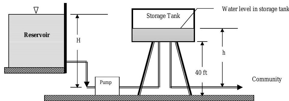
Figure \(\PageIndex{17}\): Connections between a reservoir, pump, elevated water storage tank, and community.
(a) Develop a differential equation, using only symbols, that describes how the elevation \(h\) of the water in the tank changes as a function of time. Assume that the tank is both receiving and discharging water.
(b) Determine the steady-state elevation of water in the tank, in feet, assuming the reservoir is charging the tank and the tank is simultaneously supplying the community.
(c) After a long period of steady-state operation, the flow from the reservoir stops unexpectedly. Determine the time it takes, in minutes, to lower the level of the water in the tank by 10 feet from the steady-state level found in part (b) under these conditions.
A balloon is filled with methane gas \(\left(\mathrm{CH}_{4}\right)\) at \(20^{\circ} \mathrm{C}\) and \(100 \ \mathrm{kPa}\) until the volume is \(26.4 \mathrm{~m}^{3}\). Find (a) the mass of the gas (in \(\mathrm{kg}\)) and (b) the volume (in \mathrm{m}^{3}) if the balloon rises to a height where the pressure and temperature change to \(84 \ \mathrm{kPa}\) and \(0^{\circ} \mathrm{C}\), respectively. Assume that the methane can be modeled as an ideal gas. [You may need to refer to your chemistry text or a thermodynamics text in order to find the molar mass of \(\mathrm{CH}_{4}\) and/or to review the ideal gas relation.]
A system of three tanks is connected as shown in the figure. The flow net formed by the tanks and their piping operates at steady-state conditions. The known mass flow rates are \[\dot{m}_{1} = 15 \ \mathrm{lbm} / \mathrm{s}, \ \dot{m}_{3} = 20 \ \mathrm{lbm} / \mathrm{s}, \text{ and } \dot{m}_{5} = 12 \mathrm{lbm} / \mathrm{s}. \nonumber \]
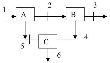
Figure \(\PageIndex{18}\): Streams of material entering and exiting a system of 3 tanks.
(a) Determine the unknown mass flow rates, in \(\mathrm{lbm} / \mathrm{s}\). (Clearly show the system(s) you use to solve for each unknown.)
(b) If you had only been given two known flow rates could you have solved the problem? What if you were only given two of the external flow rates \((1\), \(3\), and \(6)\)?
(c) What is the maximum number of unknown mass flow rates that you could solve for in this flow network if the only tool available is the conservation of mass, i.e. how many independent equations can you write for this system?
The rigid steel tank shown in the figure contains carbon dioxide gas. Initially the tank contains \(300 \mathrm{~kg}\) of gas. The tank has an internal volume of \(100 \mathrm{~m}^{3}\), one inlet, and one outlet as shown in the figure. The following information is known about the mass flow rate at the inlet:
\[\dot{m}_1 = \left\{ \begin{array}{c} \left( 10.0 \mathrm{~kg} / \mathrm{min}^{3} \right) t^{2} \text { if } 0 \leq \mathrm{t} \leq 3 \mathrm{~min} \\ 90.0 \mathrm{~kg} / \mathrm{min} \text { if } t \geq 3 \mathrm{~min} \end{array}\right. \nonumber \]
The outlet mass flow rate is a constant \(\dot{m}_{2}=90 \mathrm{~kg} / \min\) for \(t \geq 0\).
.jpg?revision=1)
Figure \(\PageIndex{19}\): System consisting of a rigid steel gas tank with one inlet and one outlet.
(a) Calculate and graph the mass of gas and the time rate of change of the mass of the gas in the tank at one minute intervals for \(0 \leq \mathrm{t} \leq 20 \mathrm{~min}\). Use an open system that corresponds with the interior volume of the tank. When, if ever, is the system at steady-state conditions?
(b) Is the density of the gas in the tank increasing or decreasing? What is the net change in the density of the gas in the tank for this 20-minute interval?
(c) How would your answer to part (a) change if you used an open system that included the walls of the tank inside your system? A qualitative discussion is acceptable.
The following equation is proposed as a model for the velocity profile in a river when the river channel is modeled as a rectangular channel of width \(2 L\) and water depth \(H\) :
\[V = V(x, y) = V_{\max } \cos \left( \frac{x}{L} \frac{\pi}{2} \right) \sin \left(\frac{y}{H} \frac{\pi}{2} \right) \nonumber \]
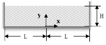
Figure \(\PageIndex{20}\): Rectangular cross-section of a river, to be used in calculating the river's velocity profile.
The following values have been measured for one river: \(V_{\max }=5 \ \text{mph}, \ L=50 \ \mathrm{ft}, \ H = 20 \ \mathrm{ft}\).
(a) Make a single graph that shows the velocity profile \(V (x,y) \) in \(\mathrm{ft} / \mathrm{s}\) for all \(y\) at \(x=0, 10, 20, 30, 40,\) and \(50 \ \text{ft}\). [Hint: Use a spreadsheet or MAPLE.]
(b) Calculate the volumetric flow rate by the two methods described below and report your answers in both cubic feet per second \( \left( \text{ft}^{3} / \mathrm{s} \right) \) and gallons per minute (\( \text{gpm}\) or \(\mathrm{gal} / \mathrm{min}\)).
Method 1 - Exact solution: Evaluate the appropriate two-dimensional (surface) integral for the cross-section. [Revisit your calculus notes/text for evaluating a surface integral.]
Method 2 - Approximate solution: Divide the cross-sectional area into \(N\) equal-sized rectangles, assume a uniform velocity inside each rectangle, calculate the approximate volumetric flow rate for each rectangle, and sum the results to get the total flow rate. Your answer will strongly depend on \(N\), so you must provide some support for why your value of \(N\) gives you a "good" answer. [Hint: Use a spreadsheet.]
(c) Calculate the average velocity for the river, in \(\text{mph}\) and \(\mathrm{ft} / \mathrm{s}\).
You have been asked to design a hydraulic system that uses a single pump to move two pistons simultaneously. As shown in the figure, the system consists of two cylinders, \(A\) and \(B\), connected by a pump. When the pump is operating at steady-state conditions, Piston \(A\) moves at \(5 \mathrm{~cm} / \mathrm{s}\).
Piston \(A\) has a diameter of \(6 \mathrm{~cm}\) and Piston \(B\) has a diameter of \(8 \mathrm{~cm}\). The hydraulic line has a diameter of \(2.5 \mathrm{~cm}\). The hydraulic lines and cylinder walls are rigid. The hydraulic fluid is incompressible with a specific gravity of \(0.8\).
.jpg?revision=1)
Figure \(\PageIndex{21}\): System consisting of two hydraulic cylinders connected by a hydrualic line passing through a pump.
(a) Starting with the conservation of mass equation and an open system of your choice, determine
- the required volumetric flow rate into the pump in \(\mathrm{m}^{3} / \mathrm{s}\) and gallons per minute (\(\text{gpm}\)) for Piston \(A\) to have the desired speed, and
- the velocity of the hydraulic fluid at the pump inlet under these conditions.
[Hint: Try a one-inlet open system with moving boundaries that contains the hydraulic fluid upstream of the pump.]
(b) Starting with the conservation of mass equation and a closed system of your choice, determine the speed of Piston \(B\) when Piston \(A\) is moving at the desired value. [Hint: Try a deforming, closed system that includes all of the hydraulic fluid.]
(c) Could you answer Part (b) using an open system? Briefly explain your answer, but you need not do the analysis.
The rigid-walled tank contains water \( \left( \rho=1000 \mathrm{~kg} / \mathrm{m}^{3} \right) \) and is open to the atmosphere on top. The tank is basically a vertical cylinder with a diameter \(D_{\text {tank}} = 3 \mathrm{~m}\). Water flows into the tank at Inlet 1 with a velocity of \(4 \mathrm{~m} / \mathrm{s}\) through a pipe of diameter \(D_1 = 0.2 \mathrm{~m}\). Water also enters the tank through Inlet 2. Water flows out of the tank through Outlet 3 at a mass flow rate of \(80 \mathrm{~kg} / \mathrm{s}\).
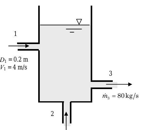
Figure \(\PageIndex{22}\): System consisting of a tank of water with two inlets and one outlet.
(a) Determine the rate of change of the water level in \(\mathrm{m} / \mathrm{s}\) if water is entering the tank through Inlet 2 at \(200 \mathrm{~m}^{3} / \mathrm{h}\) (cubic meters per hour). Is the level increasing or decreasing?
(b) For the tank to have a steady-state operating condition with the given flow rates at Inlet 1 and Outlet 3, what volumetric flow rate is required at Inlet 2?
(c) What volumetric flow rate is required at Inlet 2 if the water level in the tank rises steadily at \(10 \mathrm{~cm} / \mathrm{min}\) ?
A simple air duct with a side exhaust is shown below along with the direction of the velocity vectors at each inlet or outlet. The cross-sectional area at regions 1 and 3 are identical, \(A_{c 1} = A_{c 3} = 0.5 \mathrm{~m}^{2}\). The velocity at 2, \(V_{2}\), makes a \(20 ^{\circ}\) angle with the opening in the side of the duct \(A_{2}=0.5 \mathrm{~m}^{2}\). Measurements indicate that the flow is steady with velocities \(V_{1} = 10 \mathrm{~m} / \mathrm{s}\) and \(V_{3} = 3 \mathrm{~m} / \mathrm{s}\).
Assume that air behaves like an incompressible substance under these conditions.
(a) Determine the ratio of the volumetric flow rate at 2 to the volumetric flow rate at 1, \( \dot{V\kern-0.8em\raise0.3ex-}_2 / \dot{\kern-0.8em\raise0.3ex-}_1\).
(b) Determine the ratio of the velocity at 2 to the velocity at 1, \(V_{2} / V_{1}\).
Water enters the steady-state system (shown in the figure) at inlet 1 with a mass flow rate of \(500 \mathrm{~kg} / \mathrm{s}\) and exits the system at outlets 2 and 3.
All known areas are shown as dashed lines on the figure. The velocity \(V_{1}\) makes an angle of \(45^{\circ}\) with the known area \(A_{1}\). Velocities \(V_{2}\) and \(V_{3}\) are normal to the known areas \(A_{2}\) and \(A_{3}\), respectively.
.jpg?revision=1)
Figure \(\PageIndex{23}\): System consisting of a three-branched pipe, where water flows into one branch and out of the other two.
(a) Calculate the volumetric flow rate at outlet 3.
(b) Calculate the value of velocity \(V_{1}\) at inlet 1.
Show all steps in your solution.
An incompressible fluid enters a rectangular channel with a uniform velocity profile with an average velocity of \(V_{\text {avg}} = 3 \mathrm{~m} / \mathrm{s}\). The channel has a height \(H=1 \mathrm{~m}\) and width \(W=3 \mathrm{~m}\). As the fluid flows through the channel the velocity profile is distorted by obstructions in the flow (not shown on the figure). The distorted velocity profile is described by the equation shown on the figure. Assume all flows are steady-state.
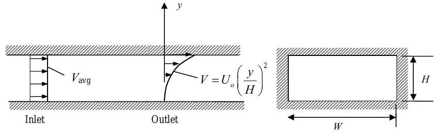
Figure \(\PageIndex{24}\): System consisting of a rectangular channel which water enters with a uniform velocity profile and exits with a distorted velocity profile given by \(V = U_0 \left( \frac{y}{H} \right) ^2\).
(a) Calculate the volumetric flow rate at the channel inlet, in \(\mathrm{m}^{3} / \mathrm{s}\).
(b) Calculate the value of the constant \(U_{0}\) in the distorted velocity profile equation, in \(\mathrm{m} / \mathrm{s}\).
Consider the hydraulic dam shown in the figure. Water is released from the dam and flows steadily over the top of the dam into a dry riverbed at a volumetric flow rate of \(200 \mathrm{~m}^{3} / \mathrm{s}\). The riverbed is \(50 \mathrm{~m}\) wide. The riverbed absorbs water, and the velocity of the water entering the ground is \(V_{\text {ground}} = 0.01 \mathrm{~m} / \mathrm{s}\) (see the arrows in the diagram).
Determine the extent of the riverbed, the length \(L\), that will be affected by the released water, i.e. how far \((L)\) will the released water flow before it is completely absorbed by the riverbed?
.jpg?revision=1)
Figure \(\PageIndex{25}\): Water flows over the surface of a dam and onto a dry riverbed, which it flows along while also being absorbed by the ground.
The tank shown below handles gasoline which has a density of \(680 \mathrm{~kg} / \mathrm{m}^{3}\). The tank is a vertical cylinder with a diameter \(D\) of 2 meters. Normally gasoline flows into the tank at Inlet 1 with a specified mass flow rate and leaves the tank at Outlet 2 .
A siphon is built into the side of the tank to prevent an overflow if there is a sudden change in the flow conditions for the tank. The siphon is simply a bent tube with one end inside the tank and the other outside the tank as shown. It will not start operating ("kick in") until the level of the gasoline in the tank exceeds the level of the siphon elbow by at least \(0.1\) meters, i.e. \(h > H+0.1 \mathrm{~m}\). Once it "kicks in", the siphon will stop working ("break") if the water level drops below the siphon inlet, i.e. \(h<(H-L)\).
Under normal conditions, the mass flow rate of gasoline into the tank is \(700 \mathrm{~kg} / \mathrm{min}\), and the gasoline level in the tank is \(h=4.0\) meters. The siphon mass flow rate is \( \dot{m}_{\text{siphon}} = \left( 300 \ \dfrac{\text{kg}}{\text{min} \cdot \text{m}^{1/2}} \right) \sqrt{h} \).
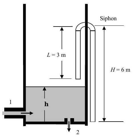
Figure \(\PageIndex{26}\): System consisting of a gasoline tank with one inlet, one outlet, and one siphon that operates when the liquid levels are sufficiently high.
(a) For some unknown reason, the outlet at 2 becomes totally blocked and the level begins to rise.
- Determine how long it will take the siphon to start working ("kick in").
- SET UP, but do not solve the differential equation that describes the rate of change of the gasoline level \(h\) during the transient to the new steady-state conditions after the siphon starts working.
- Determine the new steady-state height \(h\) of the gasoline in the tank under these conditions.
(b) After some time, the operator notices the siphon is discharging gasoline and stops the flow of gasoline into the tank; however, the tank will continue to drain until the siphon "breaks." How long will it take the siphon to "break" (stop working)?
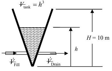
A conically-shaped tank is partially filled with an incompressible liquid (specific gravity \(SG = 0.30\)). The volume of the liquid in the tank can be described by the equation \({V\kern-0.8em\raise0.3ex-}_{\text {tank}} = h^{3}\) where \(h\) is the height of liquid in the tank (see diagram). Initially the fill valve and drain valve are both closed. (Show all your work for full credit.)
.jpg?revision=1)
Figure \(\PageIndex{27}\): System consisting of a conical tank, with a fill valve and drain valve, that contains liquid.
(a) The fill valve is opened with the drain valve closed and the tank fills with more liquid. Determine a formula for the volumetric flow rate \(\dot{V\kern-0.8em\raise0.3ex-}_{\text {Fill}}\) such that \(dh / dt\), the rate of change of the liquid level in the tank, is constant at \(1 \mathrm{~m} / \mathrm{s}\), i.e. \(dh / dt = 1 \mathrm{~m} / \mathrm{s}\).
(b) Under a different set of operating conditions, both the fill and drain valves are open with the following volumetric flow rates: \[\dot{V\kern-0.8em\raise0.3ex-}_{\text {Fill}} = (2 / \mathrm{s}) h^{3} \text { and } \dot{V\kern-0.8em\raise0.3ex-}_{\text {Drain}} = \left(50 \mathrm{~m}^{2} / \mathrm{s}\right) h \text {. } \nonumber \] Determine if there is a steady-state level for the liquid in the tank, or if it will just overflow.
(c) If the tank is just about to overflow, \(h=H\), the fill valve is automatically shut and the drain valve opened. Develop an expression for \(h\) as a function of time as liquid drains from the tank. The draining rate is the same as in part (b): \(\dot{V\kern-0.8em\raise0.3ex-}_{\text {Drain}} = \left( 50 \mathrm{~m}^{2} / \mathrm{s} \right) h\).
A boy starts drinking orange juice through a straw at the same time his mother is pouring the juice into his glass. The cross-sectional area of the cup, \(A\), is \(15 \mathrm{~cm}^{2}\) and the juice is being poured into the cup at \(20 \mathrm{~cm}^{3} / \mathrm{s}\).
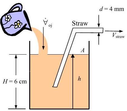
Figure \(\PageIndex{28}\): Orange juice is simulatneously poured into a glass and sucked out of it using a straw, at differing rates.
a) Determine the velocity of the orange juice in the straw required to keep the height of fluid at \(6 \mathrm{~cm}\). Comment on your answer.
b) If the mother stops pouring and the child drinks out of the straw at a time-varying rate of \(10 \mathrm{e}^{-t / \tau} \ \mathrm{cm}^{3} / \mathrm{s}\), where \(\tau = 5 \mathrm{~s}\), determine an equation for the rate of change of the height of fluid \((d h / d t)\) as a function of time.
c) What is the final height of fluid in the glass?
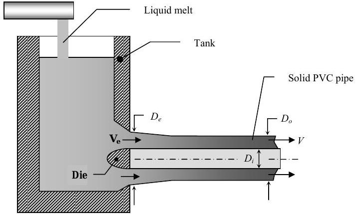
PVC pipe is manufactured using a steady-state extrusion process as shown in the figure. A liquid melt with density \(\rho_{m}\) is fed into the tank and the PVC pipe is extruded through a die in the side of the tank. As the extrusion travels to the right, the PVC material solidifies. Solid PVC has a density of \(\rho_{s}\). The finished PVC pipe has inner and outer diameter of \(D_{i}\) and \(D_{o}\), respectively, and travels to the right with a velocity of \(V\).
(a) Determine the volumetric flow rate of liquid melt that must be supplied to the tank. Express your answer in terms of \(\rho_{m}, \ \rho_{s}, \ D_{i}, D_{o}\) and \(V\).
(b) The extrusion passing through the die in the side of the tank is not solidified, but still in the liquid state. As a result, the pipe wall thickness is larger in this region. If the outer diameter of the pipe extrusion at the die (tank) exit is \(D_{e}\) as shown in the figure, find the velocity \(V_{e}\) of the liquid PVC material at this location. Express your answer in terms of the other problem variables as required.
.jpg?revision=1)
Figure \(\PageIndex{29}\): System to manufacture PVC pipe, consisting of liquid melt in a tank being extruded through a die in the tank side.
Hoosier Angels Inc. has geared up for the Christmas season and makes white plastic angels using the plastics molding system shown below.
- The feed conveyor delivers white plastic feed pellets to the feed bin. The feed has a density \(\rho_{\text {feed}}=300 \mathrm{~kg} / \mathrm{m}^{3}\).
- The feed bin is a vertical tank with a conical lower section. The cylindrical (upper) portion of the feed bin has a diameter \(D_{\text {bin}} = 1.0 \mathrm{~m}\), and a clear panel in the side of the feed bin allows the operator to observe the level \(h\) of the feed in the bin. At standard operating conditions the bin is filled so that the level of feed in the bin is \(h = h_{\mathrm{ss}} = 2.0 \mathrm{~m}\).
- The feed flows from the feed bin to the melter where it is turned into a liquid with a density \(\rho_{\text {melt}}=200 \mathrm{~kg} / \mathrm{m}^{3}\). The liquid melt then flows to the molder through the melt transfer pipe which has a diameter \(d_{\text {pipe}}=5.0 \mathrm{~cm}\).
- The angels are formed in the molder, drop onto a conveyor belt and are carried away for packaging. Each angel has a mass of 85 grams and the molding system produces 60 angels per minute.
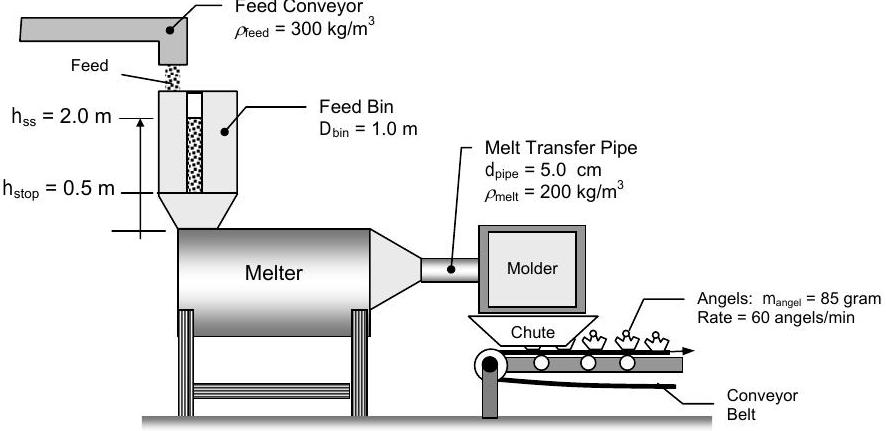
Figure \(\PageIndex{30}\): Diagram of a plastic molding system.
For questions, (a), (b), and (c) assume the process is operating at steady-state conditions.
(a) Determine the mass flow rate of feed supplied to the feed bin by the feed conveyor, in \(\mathrm{kg} / \mathrm{min}\).
(b) Determine the volumetric flow rate of feed supplied by the feed conveyor, in \(\mathrm{m}^{3} / \mathrm{min}\).
(c) Determine the average velocity of the liquid melt in the transfer pipe, in \(\mathrm{m} / \mathrm{min}\).
If the conveyor breaks down and stops supplying feed, the melter and molder can keep functioning at steady state; however, the level \(h\) of feed in the feed bin changes.
(d) Determine the rate of change of the feed level in the bin once the feed conveyor shuts down.
(e) How long after the feed conveyor shuts down can the molder continue making angels at the current rate? Assume that the feed level drops from \(h_{\mathrm{ss}}=2.0 \mathrm{~m}\) to the shutoff level \(h_{\text {stop }}=0.50 \mathrm{~m}\) during this time period.
[For full credit, you must clearly identify your system and state the pertinent assumptions in your model. Feel free to use the problem figure without redrawing it.]
A new waterfall is to be installed at one end of Speed Lake. The water level in Speed Lake is to be held constant by feeding it with water from Scum Pond. The volume flow rates into and out of Speed Lake are given by the equations \(C_{1} \sqrt{h_{1}}\) and \(C_{2} \sqrt{h_{2}}\), respectively, where \(C_{1}=700 \mathrm{~m}^{5 / 2} / \mathrm{hr}\) and \(C_{2}=1400 \mathrm{~m}^{5 / 2} / \mathrm{hr}\).
At the design conditions which produce a pleasing waterfall, \(h_{2}=0.50 \mathrm{~m}\) and the surface area of Speed Lake is \(A_{\text {surface}} = 1000 \mathrm{~m}^{2}\). By design, the surface area of Speed Lake, \(A_{\text {surface}}\), is a constant for all values of \(h_{2} \geq 0\).
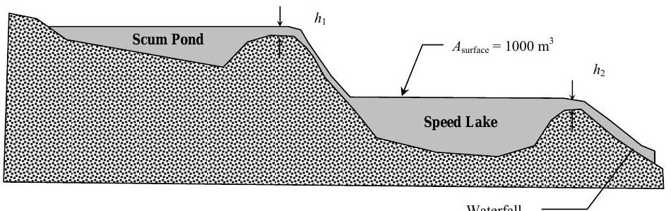
Figure \(\PageIndex{31}\): Diagram of a system consisting of a pond-fed lake, the pond, and a waterfall exiting the lake.
(a) Determine the required height \(h_{1}\) to keep the water level in Speed Lake constant at the design conditions.
(b) During long dry periods, evaporation from the surface of Speed Lake may also be important. If \(50,000 \mathrm{~kg} / \mathrm{hr}\) of water evaporates from the surface of Speed Lake, calculate the new height \(h_{1}\) required to match the design conditions.
(c) Flow into Speed Lake from Scum Pond suddenly stops. Determine the time rate of change of the water level, \(h_{2}\), in Speed Lake immediately after the flow from Scum Pond is stopped and the time it takes for \(h_{2} \rightarrow 0\). You may neglect evaporation and assume Speed Lake was at design conditions, \(h_{2}=0.50 \mathrm{~m}\), when the inlet flow stopped.
One of the important characteristics of paper towels is their ability to absorb liquid. The experimental setup shown in the figure is used to measure the absorption (storage) rate of liquid for paper towel material. The apparatus is designed so that any water stored in the sample holder is assumed to be absorbed by the paper towel.
To run the test, a dry towel sample is placed in the sample holder. Then water is allowed to drain from the supply tank into the sample holder. Excess liquid not absorbed by the towel material drains to the catch tank. The absorption (storage) rate data is developed by monitoring the liquid levels \(H\) and \(h\) as a function of time.
.jpg?revision=1)
Figure \(\PageIndex{32}\): System to test the liquid absorbancy of a paper towel sample.
(a) Develop an expression for the rate of storage of liquid in the paper towel sample \((dm / dt)\), in terms of the relevant information. A symbolic solution in terms of the problem variables is desired.
(b) When the towel material saturates, it will stop absorbing (storing) liquid. How will \(dH / dt\) and \(dh / dt\) be related when the towel saturates?
(c) Determine the time it takes to drain the liquid in the supply tank from \(H=10 \mathrm{~cm}\) to \(5 \mathrm{~cm}\) when the sample holder is empty. Under these conditions the volumetric flow rate out of the supply tank is given by the expression \( \dot{V\kern-0.8em\raise0.3ex-}_{\text {supply}} =\left( 0.30 \mathrm{~cm}^{2.5} / \mathrm{s} \right) \sqrt{H} .\)
You are given a leaky balloon (see figure) and asked to inflate it. Initially, the balloon is deflated with a volume \( V\kern-1.0em\raise0.3ex- = V\kern-0.8em\raise0.3ex-_{o} \) and a pressure inside \(P=P_{atm}\), the atmospheric pressure.
At time \(t=0\), you begin to inflate the balloon by blowing at a constant volumetric flow rate \(\dot{V\kern-0.8em\raise0.3ex-}_{B}\).
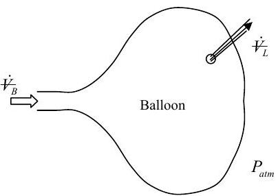
Figure \(\PageIndex{33}\): A balloon that leaks at a constant rate is being inflated at a constant rate.
The following information is also known:
- The balloon volume \(V\kern-1.0em\raise0.3ex-\) is related to the balloon pressure \(P\) by the equation: \(V\kern-0.8em\raise0.3ex- = V\kern-0.8em\raise0.3ex-_{o} + C \left( P - P_{atm} \right) \) where \(C\) is a dimensional constant and \(P_{atm}\) is the atmospheric pressure.
- The leakage volumetric flow rate, \(\dot{V\kern-0.8em\raise0.3ex-}_{L}\), is proportional to the square root of the pressure difference across the wall: \(\dot{V\kern-0.8em\raise0.3ex-}_{L} = K \sqrt{P - P_{atm}} \) where \(K\) is a dimensional constant and \(P_{atm}\) is the atmospheric pressure.
- As an approximation, assume the air to be incompressible.
- The following parameters are assumed to be given (i.e. have constant, known values): \(P_{atm}, \ \dot{V\kern-0.8em\raise0.3ex-}_{B}, \ \dot{V\kern-0.8em\raise0.3ex-}_{o}, \ C,\) and \(K\).
(a) Develop an equation for the time rate of change of the balloon volume, \(d V\kern-1.0em\raise0.3ex- / dt\). (Do not solve the equation.)
(b) Assuming that the balloon doesn't break and that you don't run out of air, what is the steady-state volume of the balloon? Give your answer in terms of the given parameters listed above.
Note: For full credit show all steps in your solution.
A two-column distillation column operates at steady-state conditions and there are no chemical reactions. The known flow rates and compositions are shown in the table.
(a) Develop the necessary equations to calculate the unknown flow rates and compositions. DO NOT SOLVE THE EQUATIONS.
(b) Solve for the unknowns.
| Stream |
Mass Flow Rate \((\mathrm{kg} / \mathrm{h})\) |
Composition (Mass %) | |||
|---|---|---|---|---|---|
| A | B | C | |||
| 1 | Feed | \(1000\) | \(20.0\) | \(30.0\) | \(50\) |
| 2 | Overhead I | \(250\) | \(62.0\) | \(5.0\) | |
| 3 | Bottoms I | ||||
| 4 | Overhead II | \(15.0\) | \(80.0\) | ||
| 5 | Bottoms II | \(0.5\) | |||
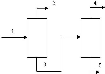
Figure \(\PageIndex{34}\): System of material streams entering and exiting a two-column distillation column.
The ItsaVegetable Co. makes ketchup for school lunchrooms using a two-stage process.
Raw tomatoes and tomato concentrate are fed into the crusher to make tomato slurry. The tomato slurry then flows into the mixer where spices are added to produce the ketchup. Additional flow rate and composition data is shown in the table.
.jpg?revision=1)
Figure \(\PageIndex{35}\): Material streams entering and exiting the two stages of a ketchup production process.
(a) Develop a sufficient set of independent equations that could be used to determine the unknown information. DO NOT SOLVE THE EQUATIONS.
(b) Solve for the unknowns.
| Stream | Contents |
Mass Flow Rate \( ( \text{lbm} / \text{h} ) \) |
Composition (Mass Fraction) | ||
|---|---|---|---|---|---|
| Tomato Solids | Water | Spices | |||
| 1 | Raw Tomato Feed | \(1000\) | \(0.500\) | \(0.500\) | \(0.000\) |
| 2 | Tomato Concentrate Feed | \(0.900\) | \(0.100\) | \(0.000\) | |
| 3 | Tomato Slurry | ||||
| 4 | Spice Feed | \(0.000\) | \(0.000\) | \(1.000\) | |
| 5 | Wet Ketchup Slurry | \(0.714\) | \(0.036\) | ||
Problem \(\PageIndex{42}\) (Revised 11 September 2006)
In the winter, a major problem in buildings is low relative humidity that occurs when dry outside air is heated. The schematic below shows an air-handling system designed to humidify outside air for ventilation and heating purposes.
The humidifier supplies conditioned air to the room. Outside air leaks into the room due to leaky windows and doors. Return air from the room is split in a splitter tee with some exhausted (exhaust air) and some recycled (recycled air). The recycled air mixes with outside air in a mixing tee. The mixed air then enters the humidifier where moisture is added.
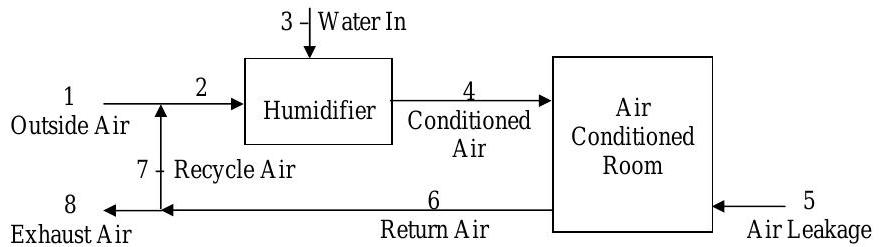
Figure \(\PageIndex{36}\): Streams of material entering and exiting the stages of an air-handling system.
(a) Develop a sufficient set of equation to calculate the unknown flow rates and compositions. DO NOT SOLVE THE EQUATIONS.
(b) Solve for the unknowns.
| Stream |
Mass Flow Rate \( ( \text{kg} / \text{min} ) \) |
Composition | ||
|---|---|---|---|---|
| Water | Dry Air | |||
| 1 | Outside Air | \(0.30 \cdot \dot{m}_4\) | \(0.004\) | |
| 2 | Mixed Air | |||
| 3 | Water In | \(1.000\) | ||
| 4 | Conditioned Air | \(1000\) | ||
| 5 | Air Leakage | \(200\) | \(0.004\) | |
| 6 | Return Air | \(0.011\) | ||
| 7 | Recycle Air | |||
| 8 | Exhaust | |||
A mixture of benzene, toluene, and xylene enters a two-stage distillation process where some of the components are recovered. The distillation process operates at steady-state conditions with operating information as shown in the table. In addition, the following information is known about the distillation process:
- \(98.0 \%\) (by weight) of the xylene that enters Column A in the feed stream (Stream 1) leaves in the intermediate stream (Stream 3)
- \(96.0 \%\) (by weight) of the benzene that enters in the feed stream (Stream 1) leaves in the bottoms of Column B (Stream 4)
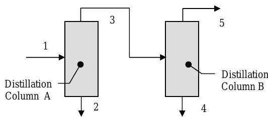
Figure \(\PageIndex{37}\): Streams of material entering and exiting the columns of a two-colum distillation system.
(a) Find a set of independent equations that can be solved for all the unknowns. Clearly identify the number of pertinent unknowns and number your equations. DO NOT SOLVE!
(b) Solve for the unknowns.
| Stream |
Mass Flow Rate \( (\mathrm{kg} / \mathrm{h}) \) |
Composition (Mass Percent) | |||
|---|---|---|---|---|---|
| Benzene | Toluene | Xylene | |||
| 1 | Feed | \(1275\) | \(30.0\) | \(25.0\) | \(45.0\) |
| 2 | Bottoms A | ||||
| 3 | Intermediate | \(0.0\) | \(1.0\) | \(99.0\) | |
| 4 | Bottoms B | \(99.0\) | \(1.0\) | \(0.0\) | |
| 5 | Tops B | ||||
A paper dryer uses treated air to lower the moisture content of wet paper. The known process information is shown in the table below the figure.
(a) Find a set of independent equations that can be solved for all the unknowns. Clearly identify the number of pertinent unknowns and number your set of equations. DO NOT SOLVE!
(b) Solve for the unknowns.
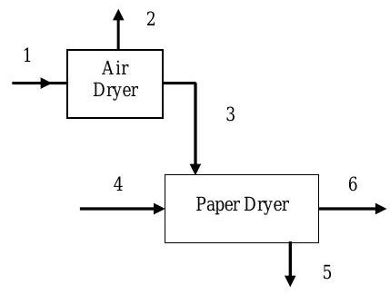
Figure \(\PageIndex{38}\): Streams of material entering and exiting the stages of a paper-drying system.
| Stream | Description | Mass Flow Rate | Composition (Mass %) | ||
|---|---|---|---|---|---|
| \( (\text{lbm} / \text{h}) \) | Paper | Water | Air | ||
| 1 | Atmospheric Air | \(10,000\) | \(0.00\) | \(0.02\) | \(99.98\) |
| 2 | Condensate | \(0.00\) | \(100.00\) | \(0.00\) | |
| 3 | Treated Air | \(0.00\) | \(0.01\) | \(99.99\) | |
| 4 | Wet Paper | \(1000\) | \(97.00\) | \(3.00\) | \(0.00\) |
| 5 | Exhaust Air | \(0.00\) | \(0.04\) | \(99.96\) | |
| 6 | Dry Paper | \(0.00\) | |||
A two-step distillation and mixing process is shown in the figure. The system operates at steady-state conditions and there are no chemical reactions. The known flow rates and compositions are shown in the table.
.jpg?revision=1)
Figure \(\PageIndex{39}\): Streams of material entering and exiting the stages of a distillation and mixing process.
(a) Develop the necessary equations to calculate the unknown flow rates and compositions. DO NOT SOLVE THE EQUATIONS.
(b) Solve for the unknowns.
| Stream | Mass Flow Rate | Composition (Mass %) | ||
|---|---|---|---|---|
| \( (\text{kg} / \text{h}) \) | \(A\) | \(B\) | ||
| 1 | Feed | \(100\) | \(50.0\) | \(50.0\) |
| 2 | Distillate | \(90.0\) | \(10.0\) | |
| 3 | Concentrate | |||
| 4 | Diluent | \(30.0\) | \(70.0\) | |
| 5 | Product | \(90\) | \(26.0\) | |
A glycerol plant operates at steady-state conditions and treats a glycerol solution (1) by feeding it into an extraction tower with an alcohol solvent (3). Two streams leave the extraction tower: a raffinate stream (2) and an extract stream (4). The extraction tower involves four compounds: glycerin, salt (NaCl), butyl alcohol, and water.
The extract stream (4) is fed into a distillation tower. No salt enters the distillation tower, and the distillation process involves only three compounds: glycerin, butyl alcohol, and water. A distillate stream (5) and a bottoms stream (6) leave the distillation tower. Detailed information about the known flow rates and mass compositions is shown in the table.
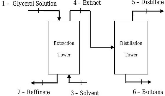
Figure \(\PageIndex{40}\): Streams of material entering and exiting an extraction and distillation system.
(a) Develop a sufficient set of equations to determine the unknown flow rates and compositions.
(b) Solve for the unknowns.
| Stream | Mass Flow Rate | Composition (Mass %) | ||||
|---|---|---|---|---|---|---|
| \( ( \mathrm{lbm} / \mathrm{h} ) \) | Glycerin | Salt (\(\text{NaCl}\)) | Butyl Alcohol | Water | ||
| 1 | Glycerol Solution | \(1000\) | \(10.00\) | \(3.00\) | \(\cdots \cdots \cdots\) | \(87.00\) |
| 2 | Raffinate | \(1.00\) | \(1.00\) | |||
| 3 | Solvent | \(1000\) | \(\cdots \cdots \cdots\) | \(\cdots \cdots \cdots\) | \(98.00\) | \(2.00\) |
| 4 | Extract | \(0.00\) | ||||
| 5 | Distillate | \(\cdots \cdots \cdots\) | \(\cdots \cdots \cdots\) | \(95.00\) | \(5.00\) | |
| 6 | Bottoms | \(25.00\) | \(\cdots \cdots \cdots\) | \(\cdots \cdots \cdots\) | \(75.00\) | |
Salad dressing \({ }^{1}\) is made in a two-stage mixing process as shown in the figure below. A sugar solution is mixed with pure water and crushed herbs in the first stage. The exiting stream is mixed with vinegar and olive oil in the second stage. Known flow rates and compositions are listed in the table.
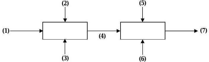
Figure \(\PageIndex{41}\): Streams of material entering and exiting the two stages of a mixing process.
| Stream | Mass Flow Rate | Composition (Mass %) | |||||
|---|---|---|---|---|---|---|---|
| \( (\text{lbm} / \text{h}) \) | Sugar | Herbs | Vinegar | Oil | Water | ||
| 1 | Sugar solution | \(0.3\) | \(\cdots\) | \(\cdots\) | \(\cdots\) | \(0.7\) | |
| 2 | Herbs | \(\cdots\) | \(1.0\) | \(\cdots\) | \(\cdots\) | \(\cdots\) | |
| 3 | Water | \(\cdots\) | \(\cdots\) | \(\cdots\) | \(\cdots\) | \(1.0\) | |
| 4 | Mixture | ||||||
| 5 | Vinegar | \(\cdots\) | \(\cdots\) | \(1.0\) | \(\cdots\) | \(\cdots\) | |
| 6 | Oil | \(\cdots\) | \(\cdots\) | \(\cdots\) | \(1.0\) | \(\cdots\) | |
| 7 | Dressing | \(500\) | \(0.10\) | \(0.09\) | |||
a) It is desired to have equal amounts (by mass) of water, oil and vinegar in the dressing. What are the required mass fractions of vinegar, oil and water in the exit stream (7)?
b) Develop a set of equations that could be used to solve for all unknown mass flow rates as well as the mixture composition of stream (4).
c) Solve for the unknowns.
{ }^{1} Crushed herbs include basil, thyme, rosemary and just a hint of saffron. Of course, only the finest red wine vinegar and extra-virgin olive oil go into any ConAps salad dressing.