
6.4: Problems
- Page ID
- 81502

The bracket \(BCD\) is hinged at \(C\) and attached to a control cable at \(B\). For the loading shown, determine (a) the tension in the cable, (b) the reaction at \(C\). [Remember to explicitly select a system, apply the basic equations, and state your simplifying assumptions.]
.png?revision=1&size=bestfit&width=735&height=365)
Figure \(\PageIndex{1}\): A bracket is loaded with two point forces.
(Adapted from Beer & Johnston, Dynamics, 6th ed., McGraw-Hill)
Grain falls from a hopper onto a chute \(C B\) at the rate of \(240 \ \mathrm{lbm} / \mathrm{s}\). It hits the chute at \(A\) with a velocity of \(20 \ \mathrm{ft} / \mathrm{s}\) and leaves at \(B\) with a velocity of \(15 \ \mathrm{ft} / \mathrm{s}\), forming an angle of \(10^{\circ}\) with the horizontal. Knowing that the combined weight of the chute and of the grain it supports is \(600 \ \mathrm{lbf}\) and acts at \(G\), determine the reaction of the roller support \(B\) and the components of the reaction at the hinge \(C\).
.jpg?revision=1)
Figure \(\PageIndex{2}\): Side view of grain falling onto a curved chute and exiting in an angled stream.
[Be sure to sketch your system carefully so that you can see what is happening. Do not assume that you know any dimensions other than the ones given to you in the problem statement and figure. Also note that you can calculate the angular momentum about any point inside or on the boundary of the system. It is usually best to pick the point that minimizes the calculations or where the transports of angular momentum are easiest to see.]
(Adapted from Pestel & Thomson, Statics, McGraw-Hill)
For the clamping device shown in the figure, determine the forces \(\mathbf{F}_{1}\) and \(\mathbf{F}_{2}\).
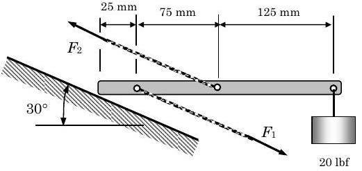
Figure \(\PageIndex{3}\): A clamping device experiences two unknown tension forces.
(Adapted from Pestel & Thomson, Statics, McGraw-Hill)
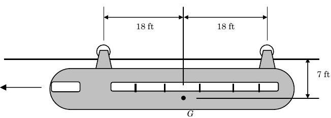
A monorail car with the dimensions shown in the figure is driven by only the front wheel. If the coefficient of static friction between the wheel and the rail is \(0.60\), determine the maximum acceleration possible for the car.
.jpg?revision=1)
Figure \(\PageIndex{4}\): A monorail car hangs below a track, supported by its wheels.
- Answer
-
\(0.340 \mathrm{~g}\)
The loaded trailer shown in the figure has a mass of \(900 \mathrm{~kg}\) with a center of mass at \(G\) and is attached at \(A\) to a rear-bumper hitch. Pertinent dimensions are given on the diagram.
(a) Determine the vertical component of the hitch force acting on the trailer at \(A\) when the trailer is stationary. Give both the magnitude, in newtons, and the direction of the force.
(b) If the car accelerates to the right at the rate of \(4.5 \mathrm{~m} / \mathrm{s}^{2}\), determine the vertical component of the hitch force acting on the trailer at \(A\). Neglect the small friction force exerted on the relatively light wheels. Give both the magnitude, in newtons, and the direction of the force.
.jpg?revision=1)
Figure \(\PageIndex{5}\): Side view of a loaded trailer.
You have been challenged by your buddies to balance a broomstick in your hand. So that you don't embarrass yourself, you've decided to do some analysis before you put on a show.
As a first approximation, you assume that the broomstick can only move in the plane of the paper. The broom has a mass \(m = 2.0 \mathrm{~lbm}\) and an overall length \(L = 5 \mathrm{~ft}\). The center of mass of the broom, including the bristles, is located a distance \(0.6 L\) from the end of the broom handle
If you start to balance the broom when it leans an angle \(\theta=30^{\circ}\) from the vertical, your challenge is to move your hand horizontally so that the broom maintains this orientation, i.e. it undergoes linear translation. Since you cannot grab the broom, assume that your hand can only resist forces in the \(x\) - and \(y\)-directions.
For these conditions, determine (a) the magnitude and direction of the reaction of your hand on the broom, and (b) the direction and magnitude of the horizontal acceleration of the broom.
.png?revision=1)
Figure \(\PageIndex{6}\): A broom is balanced on a hand via the end of its broomstick.
A Pelton wheel turbine is used extract energy from a stream of flowing water. When it is operating at steady-state conditions, the water stream enters the rotating turbine wheel as shown with velocity \(V_{1}\) and leaves the turbine with velocity \(V_{2}\) at an angle \(\theta\). Under these conditions, the turbine wheel rotates about the axis through point \(O\). The black dot at \(O\) represents the turbine shaft. For steady-state operation, two reaction forces \(R_{\mathrm{x}}\) and \(R_{\mathrm{y}}\) and a torque (or moment) \(M_O\) must be applied to the shaft at point \(O\).
If the mass flow rate is \(50 \mathrm{~kg} / \mathrm{s}\) and \(V_{1}=V_{2}=30 \mathrm{~m} / \mathrm{s}\), determine the two reaction forces and torque at \(O\) if \(\theta=\) (a) \(0^{\circ}\), (b) \(30^{\circ}\), (c) \(60^{\circ}\), (d) \(90^{\circ}\), (d) \(120^{\circ}\), (e) \(150^{\circ}\), and (f) \(180^{\circ}\).
.jpg?revision=1)
Figure \(\PageIndex{8}\): Water runs along a section of a wheel turbine, turning it clockwise.
(Adapted from Bedford & Wallace, Dynamics, 2nd ed., Addison-Wesley)
The slender bar weighs \(10 \ \mathrm{lbf}\) and the disk weighs \(20 \ \mathrm{lbf}\). The coefficient of kinetic friction between the disk and the horizontal surface is \(0.1\). If the disk has an initial counterclockwise angular velocity of \(10 \ \mathrm{rad} / \mathrm{s}\), how long does it take for the disk to stop spinning.
.jpg?revision=1)
Figure \(\PageIndex{9}\): An angled bar has one end pinned to a wall and the other pinned to a disk resting on the ground.
Water flows out of a fire hydrant with a velocity of \(50 \ \mathrm{ft} / \mathrm{s}\) and a volumetric flow rate of \(1000 \ \mathrm{gpm}\). The water pressure at the inlet to the hydrant is \(200 \ \mathrm{psia}\) and the atmospheric pressure is \(14.7 \ \mathrm{psia}\). At the base of the hydrant the bolts must resist a normal force holding the hydrant down, a shear force parallel to the ground, and a couple trying to rotate the hydrant off its base. Calculate these reactions assuming steady-state conditions. Assume the density of water is \(62.4 \ \mathrm{lbm} / \mathrm{ft} ^{3}\).
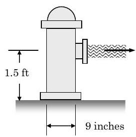
Figure \(\PageIndex{9}\): Side view of a fire hydrant with water exiting its nozzle in a horizontal stream.
The frame shown supports part of a small building. Knowing that the tension in the cable is \(150 \ \mathrm{kN}\), determine the reaction at the fixed end \(E\) (forces and moment).
.jpg?revision=1)
Figure \(\PageIndex{10}\): A frame consisting of two beams and two support cables is loaded with several point loads.
A high-speed jet of air issues from the nozzle \(A\), which has a diameter of \(40 \mathrm{~mm}\), with a velocity of \(240 \mathrm{~m} / \mathrm{s}\) and mass flow rate of \(0.36 \mathrm{~kg} / \mathrm{s}\) and impinges on the vane \(OB\), shown on its edge view. The vane and its right angle extension have negligible mass compared to the attached \(6 \mathrm{-kg}\) cylinder, and are freely pivoted about a horizontal axis through \(O\). The air density under the prevailing condition is \(1.206 \mathrm{~kg} / \mathrm{m}^3\).
Determine:
(a) the steady state angle \(\theta\) assumed by the vane with the horizontal, and
(b) the reaction forces at \(O\).
.jpg?revision=1)
Figure \(\PageIndex{11}\): A jet of air travels horizontally until it impacts a slanted surface, moving at constant speed throughout.
A ball with mass \(m=5 \ \mathrm{lbm}\) is mounted on a horizontal rod that is free to rotate about a vertical shaft as shown in the figure. In the position shown (position \(A\) ), the rod rotates and the ball is held by a cord attached to the shaft. In this state, the speed of the ball is \(V_1=24 \ \mathrm{in} / \mathrm{s}\). The cord is suddenly cut and the ball moves to the position \(B\) as the rod continues to rotate. Neglecting the mass of the rod, determine the speed of the ball after it has reached the stop \(B\). Be careful to show all of your work.
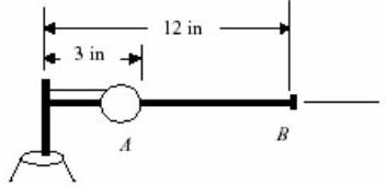
Figure \(\PageIndex{12}\): Two instantaneous positions of a ball in relation to a rotating rod on a shaft.
(From Dynamics by Beer and Johnson)
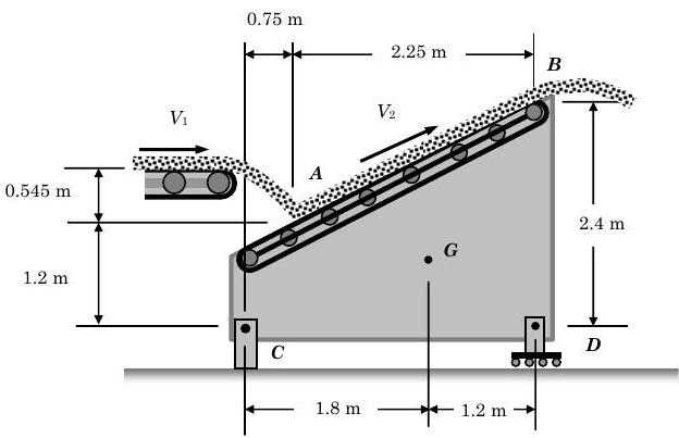
Coal is being discharged from a horizontal conveyor belt at the rate of \(120 \mathrm{~kg} / \mathrm{s}\). It is received at \(A\) by a second belt which discharges it again at \(B\). Knowing that \(v_{1}= 3 \mathrm{~m} / \mathrm{s}\) and \(\mathrm{v}_{2}=4.25 \mathrm{~m} / \mathrm{s}\), and that the second belt assembly and the coal it supports have a total mass of \(472 \mathrm{~kg}\), determine horizontal and vertical components of the reactions at \(C\) and \(D\).
.jpg?revision=1)
Figure \(\PageIndex{13}\): Coal falls off a horizontal conveyor belt onto a diagonal one where it is again discharged.
A conveyor system is fitted with vertical panels, and a \(300 \mathrm{~mm}\) rod \(AB\) of mass \(2.5 \mathrm{~kg}\) is lodged between the panel as shown. Assume all the surfaces are smooth. Knowing the acceleration of the panel and the rod is \(1.5 \mathrm{~m} / \mathrm{s}^{2}\) to the left, determine the reactions of the carrier on the rod at \(C\) and \(B\).
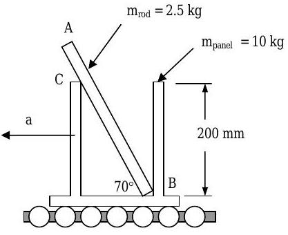
Figure \(\PageIndex{14}\): A rod rests against two vertical panels traveling along a conveyor belt.
(Modified from Dynamics by Beer and Johnson)
The forklift shown weighs \(2250 \ \mathrm{lbf}\) and is used to lift a crate of weight \(\mathrm{W}=2500 \ \mathrm{lbf}\). The coefficient of static friction between the crate and the fork lift is \(0.3\).
Determine:
(a) the maximum deceleration the forklift can have for the crate not to slip, and
(b) the maximum deceleration the forklift can have for the forklift not to tip.
(c) If the truck is moving to the left at a speed of \(10 \ \mathrm{ft} / \mathrm{s}\) when the brakes are applied, determine the smallest distance in which the truck can be brought to a stop if the crate is not to slide and if the truck is not to tip forward.
.jpg?revision=1)
Figure \(\PageIndex{15}\): Side view of a two-axle forklift lifting a crate.
Part (a) Three forces are applied to the L-shaped plate shown in the figure. All forces are applied in the plane of the paper.
(i) Determine the moment of each force about Point \(O\) and the sum of the moments about Point \(O\), in \(\text{lbf-ft}\).
(ii) Determine the moment of each force about Point \(P\) and the sum of the moments about Point \(P\), in \(\text{lbf-ft}\).
(iii) Do any of the forces applied to the plate form a couple? If the answer is yes, which ones?
[Note: Remember to indicate both the direction (label CW or CCW, or use arrows) and magnitude of all vector quantities.]
.png?revision=1)
Figure \(\PageIndex{16 \text{a}}\): Point forces are applied at different locations on an L-shaped plate.
Part (b) Two forces act on the planar, rigid body shown in the figure.
Determine the individual moment of each force about the point \(O\) and the sum of the moments about point \(O\) in \(\mathrm{N}-\mathrm{m}\). Remember to indicate the direction and magnitude of all vector quantities.
Figure \(\PageIndex{16 \text{b}}\): Point forces are applied at different locations on an irregularly shaped plate.
Consider the pulley-mass system shown in the figure. The diameters of the large and small pulley are \(D = 0.5 \mathrm{~m}\) and \(d = 0.25 \mathrm{~m}\), respectively. Both pulleys turn together around the same axle, point \(P\).
(a) If the pulleys are locked by a brake and cannot turn, the weight of each block produces a moment about point \(P\). Determine the net moment about point \(P\) due to the stationary blocks, in \(\text{N-m}\).
(b) If the pulleys turn together at the rate of \(2.0\) radians per second in the direction shown, i.e. \(\omega=2.0 \mathrm{rad} / \mathrm{s}\) in the direction shown, each of the blocks has angular momentum and linear momentum. Determine the following for each block:
- the velocity, in \(\mathrm{m} / \mathrm{s}\),
- the linear momentum, in \(\mathrm{kg-m} / \mathrm{s}\), and
- the angular momentum of each mass with respect to axle point \(\mathrm{P}\), in \(\mathrm{kg-m}^{2} / \mathrm{s}\).
Remember to indicate both the magnitude and direction of all vector quantities.
.jpg?revision=1)
Figure \(\PageIndex{17}\): Two weights are suspended from two pulleys through which a single axle passes.
A horizontal force \(\mathbf{P}\) acts on a cabinet that rests on a floor as shown. The cabinet weighs \(120 \ \mathrm{lbf}\). It is known that the coefficient of static friction is \(\mu_{\mathrm{s}}=0.30\) and the coefficient of kinetic friction is \(\mu_{\mathrm{k}}=0.24\).
(a) If slipping impends, what is the magnitude of \(\mathbf{P}\) ?
(b) If tipping impends,
(i) what is the magnitude of \(\mathbf{P}\), and
(ii) at what point will the resultant floor reaction act?
(c) What is the smallest magnitude of \(\mathbf{P}\) that will cause the cabinet to move, i.e. either tip or slip?
.jpg?revision=1)
Figure \(\PageIndex{18}\): A horizontal force is applied to a tall cabinet resting on the floor.
Water flows steadily through the elbow-nozzle assembly shown in the figure. The assembly is in the vertical plane (the plane of the paper) and gravity acts as indicated. The assembly is supported entirely by the flange bolts which must resist forces in the \(x\)-and \(y\)-directions as well as a moment. For purposes of analysis, you may assume that all flange reactions are concentrated at the dark "dot" at the centerline of the flange. The available information about the geometry and operating conditions of the assembly are shown in the figure.
Determine the forces and moment (the reactions) at the flange to support the elbow-nozzle assembly.
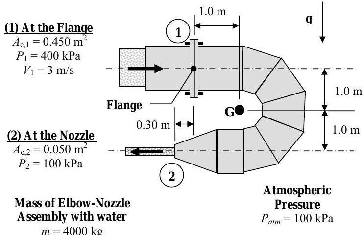
Figure \(\PageIndex{19}\): Water flows from a horizontal pipe into an elbow-nozzle assembly, connected to the pipe by a flange.
A cyclist is traveling on a level road at a speed \(V=15 \mathrm{~m} / \mathrm{s}\). The combined mass of the person and bicycle shown in the figure is \(m=77 \mathrm{~kg}\). The location of the combined center of mass relative to the wheels is also shown.
Suddenly the cyclist uses the handlebar brakes to stop the bike. If she only applies the front brakes, determine
(a) the maximum horizontal force of the ground (the braking force) on the bike at Point \(A\) that can be applied without the bike flipping (neglect any horizontal force exerted by the ground on the rear wheel), and
(b) the corresponding deceleration of the cyclist and bike measured in \(g\)'s, e.g. \(8.3g\), and
(c) the maximum allowable value of the kinetic friction coefficient between the front wheel and the ground if the front wheel locks under these conditions and slides on the ground.
.jpg?revision=1)
Figure \(\PageIndex{20}\): System consisting of a cyclist and bike, traveling at a constant velocity.
As part of a school bus safety test program, school buses are being tested for potential roll-over hazards. To test the bus, it is placed on a \(1000\text{-pound}\) moveable concrete pad that rolls freely without friction. The horizontal motion of the pad is produced by a hydraulic ram which pulls the pad to left. A \(5000 \text{-pound}\) school bus is placed on the pad as shown in the figure
(a) Assuming the bus does not slip on the pad, determine the minimum value of the horizontal acceleration \((d V / d t)\) of the pad in the direction indicated that will cause the bus to tip, in \(\mathrm{ft} / \mathrm{s}^{2}\).
(b) Determine the force, in \(\mathrm{lbf}\), that the ram must apply to the platform to produce the acceleration found in part (a).
(c) Determine the minimum static coefficient of friction between the tires and the concrete pad that is required to keep the bus from slipping on the moving pad.
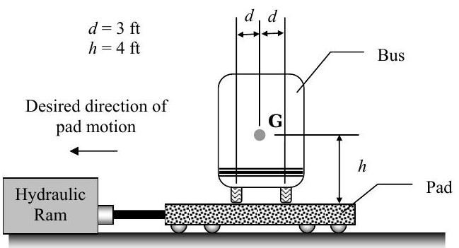
Figure \(\PageIndex{21}\): End-on view of a school bus, placed on a rolling pad that is pulled to the left.
A manufacturer of handheld showerheads uses the setup shown in the figure to test the "handling" characteristics of their showerheads. For the tests, the showerhead is hung from a vertical water-supply pipe using a pinned-joint connection that can only resist horizontal and vertical forces.
Water enters the showerhead at \(B\) with a purely vertical velocity of \(1.00 \ \mathrm{ft} / \mathrm{s}\) and a volumetric flow rate of \(0.0050 \ \mathrm{ft}^{3} / \mathrm{s}\). The water pressure in the water supply line is \(35 \ \mathrm{psia}\).
At the spray outlet, the water velocity is \(25 \ \mathrm{ft} / \mathrm{s}\) and the pressure is atmospheric (\(P_{\mathrm{atm}}=14.7 \ \mathrm{psia}\)).
The test showerhead weighs \(1.3 \ \mathrm{lbf}\). The density of water can be assumed to be \(62.4 \ \mathrm{lbm} / \mathrm{ft}^{3}\)
For these steady-state test conditions, determine
(a) the angle \(\theta\) the showerhead makes with the vertical, and
(b) the horizontal reaction force at the pinned joint.
.jpg?revision=1)
Figure \(\PageIndex{22}\): Water moves through a system consisting of a shower head pinned to a vertical pipe.
A steel pipe \(B C\), of length \(L_{p}\) with a mass \(m_{p}\), is attached to the rear bumper of a truck using a lightweight rope \(A B\) of length \(L_{r}\). The coefficient of kinetic friction at point \(C\) is \(\mu_{\mathrm{k}}\). The angles that the rope and the steel pipe make with the horizontal are constant and shown on the figure.
Determine the constant acceleration of the truck \(a_{\text {truck}}\) and the tension in the rope \(T\) required to maintain these conditions.
SET UP BUT DO NOT SOLVE. Clearly identify your unknowns and the set of equations you would use to solve for the unknowns.
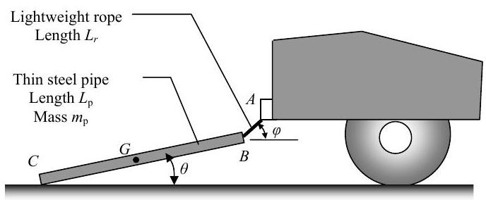
Figure \(\PageIndex{23}\): A pipe with one end resting on the ground is connected to a truck bumper by a taut rope.
The air-handling unit (AHU) shown in the figure is attached to a fixed support that ultimately rests on the roof. The fixed support corresponds with the center of mass \(G\) of the AHU. The AHU weighs \(500 \ \mathrm{lbf}\).
The expected steady-state operating conditions are shown on the figure. Note that the pressure around the AHU is everywhere atmospheric, \(P_{\text {atm}}=14.7 \ \mathrm{psia}\), except at the air inlet (state 1) where \(P_{1}=14.6 \ \mathrm{psia}\). You may assume that the air density is constant and uniform at \(\rho_{\text {air}}=0.075 \ \mathrm{lbm} / \mathrm{ft}^{3}\).
Determine the reactions at point \(G\) required to support the AHU.
.jpg?revision=1)
Figure \(\PageIndex{24}\): An air handling unit with one inlet and one outlet is suspended via a fixed support through its center of mass.
The dragster has a mass of \(1200 \mathrm{~kg}\) and a center of mass at \(G\). A braking parachute is attached at \(C\) and, when released, provides a horizontal braking force of \(F=k_{\mathrm{O}} V^{2}\) where \(k_{\mathrm{O}}=1.6 \mathrm{~N} \cdot \mathrm{s}^{2} / \mathrm{m}^{2}\) and \(V\) is the dragster velocity. If the parachute is deployed when the dragster is traveling too fast, there is a danger that the dragster will flip.
You may neglect the mass of the wheels and assume the engine is disengaged so that the wheels are freely rolling (so there is no horizontal force between the wheels and the ground) when the parachute is released.
a) Determine the critical speed (the maximum safe speed) the dragster can have such that the wheels at \(B\) are on the verge of leaving the ground when the parachute is released
b) If the dragster is traveling at the critical speed when the parachute is deployed, determine the distance it will travel before it stops. Does your answer make sense? If not, what do you think is the problem?
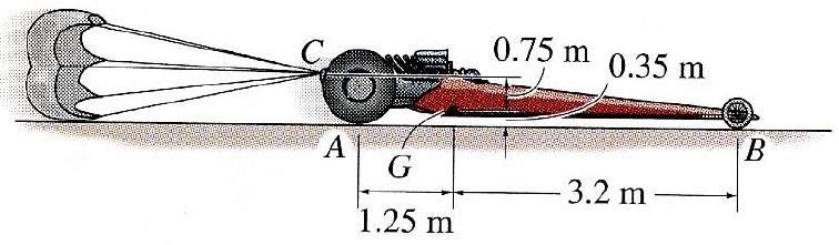
Figure \(\PageIndex{25}\): A dragster traveling to the right deploys a parachute from its rear.
The girder shown in the figure weighs \(4000 \mathrm{~N}\) and the motor weighs \(1200 \mathrm{~N}\). The motor is hoisting a load that weighs \(8000 \mathrm{~N}\). (Assume mass moment of inertia of the motor \(I_{\text {motor}}\) is negligible.)
Determine the reactions at \(A\) and \(B\) if the motor is raising the load and the load has an acceleration of \(1.5 \mathrm{~m} / \mathrm{s}\) upward.
.jpg?revision=1)
Figure \(\PageIndex{26}\): A motor resting on a girder turns to raise a load.
A jet of water with density \(\rho\) hits a hinged flap with a mass \(m\) as shown in the figure. The velocity of the water of both the incoming and outgoing jet is \(V_{\text {jet}}\). The incoming water jet is circular with a diameter \(d\). Known dimensions are given in the figure.
a) Find the angle \(\theta\) that the stationary flap makes with the horizontal. Express your answer in terms of the known quantities.
b) Find the horizontal and vertical reaction forces at the pin connection \(A\). You may assume that \(\theta\) is known from part (a).
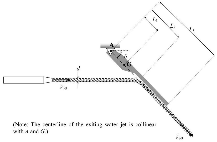
Figure \(\PageIndex{27}\): Water strikes a hinged, angled flap and runs down it.
Moo's Dairy has entered the annual Dairy Drag Race at the State Fair. His drag racer is a fully-loaded milk truck shown in the figure. When fully loaded, the milk truck weighs \(5000 \ \mathrm{lbf}\). The truck is a rear-wheel drive vehicle, and the front tires provide negligible frictional drag when rolling.
The maximum traction between the tires and the road occurs when there is no slip between the tires and the road, i.e. the force between the road and the tires is due to static friction. The static coefficient of friction between the rubber tires and the concrete pavement is \(\mu_{\mathrm{s}}=0.80\).
(a) Determine the reactions between the tires and the road at points \(A\) and \(B\), in \(\mathrm{lbf}\), when the truck is stationary.
(b) Determine the maximum acceleration possible for the fully-loaded, rear-wheel drive milk truck, in \(\mathrm{ft} / \mathrm{s}^{2}\) or in \(g\)'s. Also determine the corresponding reactions at points \(A\) and \(B\), in \(\mathrm{lbf}\). Is there any danger of the truck tipping under these conditions?
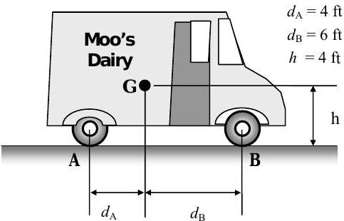
Figure \(\PageIndex{28}\): Side view of a milk truck on level ground.