
14.15: Optics
- Page ID
- 45597
Light and Optics
Optics is technically the study of light and its properties when interacting with different materials. Note that the here light is rather broad and includes a large portion of the electromagnetic spectrum of which only a small part is visible.
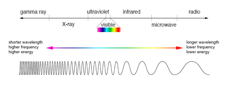 |
| A description of the electromagnetic spectrum using wavelength, frequency, and energy. Note that visible is just a very small part of the electromagnetic spectrum. Most wavelengths (not just visible) can be "bent" to work with a parabolic (or close to parabolic) "mirror" to produce telescopes. This image is from NASA's Image the Universe. |
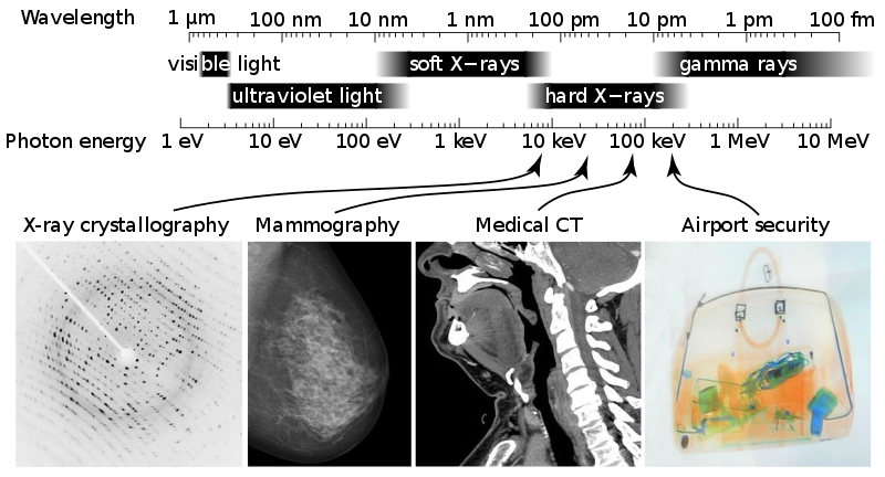 |
| A different perspective on the electromagnetic spectrum with applications in the X-ray region of the electromagnetic spectrum (X-ray crystallography, mammography, computed tomography (CT or CAT) scan, and security). This image is from Wikipedia credited to Ulflund, Del45, Nevit Dilmen, ChumpusRex, and Mattes. |
Here we will explore just a few aspects of optical engineering through the discussion of lenses and mirrors. You will do basic study of optics in your physics class, but in general only electrical engineers will delve into the topic more thoroughly (and if you want to go really in-depth then you need to study graduate physicists). This topic can get intense, but not herein.
Snell's law
The first law to learn in optics and the most important is Snell's law1 which describes refraction and reflection mathematically. From a more general wave front description refraction is described by a form of least time known as Fermat's principle2.
Snell's law of reflection simple states that the angle of incident of a light ray is equal to the angle of reflection. Snell's law of refraction states that the incident ray will bend as a function of index of refraction (a property of optical materials which is wavelength dependent) and the sine of the angles.
\[n_1(\lambda)sin(\theta_1)=n_2(\lambda)sin(\theta_2)\]
Sometimes this is expressed with the assumption of a visible wavelength that corresponds close to yellow and the assumption that within a reasonable visible area the wavelength is constant (this is not a good assumption in the blue-violet range).
\[n_1 sin(\theta_1) = n_2 sin(\theta_2)\]
 |
|
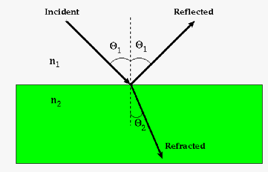
This is a cartoon describing the relationship between incident, reflected, and refracted waves. The arrows describe light in a manner we call ray optics. Real waves are described by wave fronts, just like waves from the ocean. Ray optics works fairly well and is easier to use for most cases but not all. Here note the incident angle of the light ray is equal to the reflected angle of the light ray and the refracted ray is "bent" based of the Snell's law of refraction. |
Important in this is the idea of the index of refraction of materials. The speed of light, c, is normally reported as the speed of light in a vacuum. However, technically, the speed of light is actually dependent on the material in travels in. This dependency is described by the index of refraction.
\[c_m = \frac{c_v}{n_m(\lambda)}\]
where \(c_m\) is the speed of light in a particular medium, \(c_v\) is the speed of light in a vacuum, and \(n_m\) is the index of refraction of material m.
This property of refraction can lead to some interesting results such as internal reflection of light in a material. A careful calculation of the index of refraction and the angle of incident will lead to this effect. This is what is used in fiber optics for communications (though in generally it is a bit more complex as fibers are usually multi-clad). Light pipes (or light tubes) use similar principles but are usually a more complex as they could involve prisms and mirrors as well.
 |
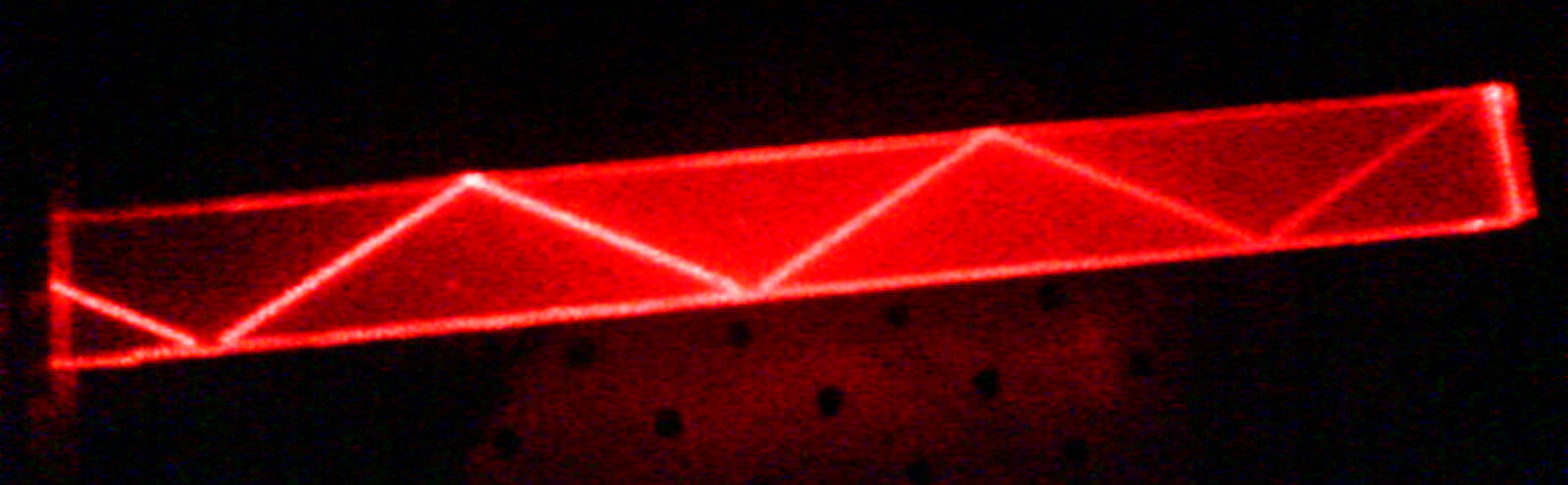 |
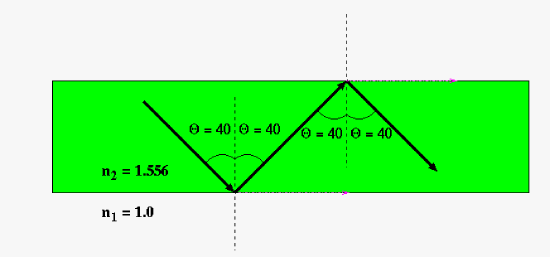
| This is a cartoon describing internal reflection (note the "refracted" portion of the wave is along the surface in pink at 90 degrees). Here the indices of refraction and angle of reflection was determined to assure internal reflection. The critical angle will be defined by the index of refraction (note since this is wavelength dependent you would need to know the wavelength of light for any application). The equation for the critical angle: \(\theta_c = arcsin\left(\frac{n_2}{n_1}\right)\) | Example of internal reflection in PMMA (plexiglass) By Sai2020 - own work, Public Domain, https://commons.wikimedia.org/w/index.php?curid=5712691...for size reference you can use the optical table (which you should have reviewed in your laboratory design project) under the PMMA. |
Basic Optical Elements
The basic optical elements are lenses and mirrors. In this brief section we will just give a sketch on those elements.
 |
| There are many optical elements but for a basic description the divergent lens, convergent lens, and parabolic mirror are the conceptually the most important. The convergent lens is as its name implies: it converges light. This lens is the most oft mentioned lens as it is used in basic descriptions of refractor telescopes and microscopes. The divergent lens is as its name implies: it diverges light. This lens is usually used in telescopes and cameras. Parabolic mirrors or almost parabolic mirrors (made more hyperbolic to reduce aberrations - at a cost however) are used in reflecting telescopes such as Hubble Space Telescope. |
Mirrors
There are a number of type of mirrors that are used in science and engineering. The flat mirror is obvious, but parabolic or close to parabolic mirrors are useful for reflecting telescopes. In particular a parabolic mirror will focus parallel light onto a focal point which can be used for astronomical observation (light from distance stars, etc. is essentially parallel). This can also be used in reverse where a light is used at the focal point and parallel light rays are projected out. This idea is used in flashlights and spotlights (theater lighting).
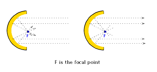 |
| This cartoon of a parabolic mirror shows how parallel light (shown with ray tracing) reflects to a singular point called the focal point. This is particularly useful for astronomical observations (though two mirrors are usually used one concave and another convex normally). Likewise light from a focal point reflects off the mirror in a parallel direction. This is what makes flashlights and spotlights so effective. The parabolic mirror is a convergent optical element (as opposed to the convex mirror which is divergent - see below for a telescope example). |
Lenses
Lenses are used in an array of optical devices including camera, telescopes (refracting type telescope though some components in a reflecting telescope might have lenses as well), Raman spectrometers (with mirrors as well), microscopes, and a host of other optical devices. There are two main types of lenses: converging and diverging. The converging are the most widely known as that is the basis for magnifying glasses which almost everyone has used in their lifetime. Converging lenses are based-off convex lens (take note that convex mirrors are divergent, so be careful which element you are discussing) and can be plano-convex, bi-convex, and positive meniscus and diverging lenses are based-off concave lens and can be plano-concave, bi-concave, and positive meniscus.
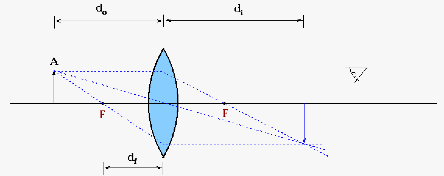
Ray tracing is one method to describe how the path of waves (light in the case of optics, though for seismology they would use s and p waves) through a medium. Usually the wave front is not included in this description for simplification. Here we will describe ray tracing or a bi-convex and bi-concave lens assuming the lenses are fairly thin (thin lens equation: \(\frac{1}{f} = \frac{1}{d_o} + \frac{1}{d_i}\) where \(d_o\) is the distance of the real object from the center of the lens, \(d_i\) is the distance of the image object from the center of the lens, and \(d_f\) is the focal distance from the center of the lens as seen in the figure below).
 |
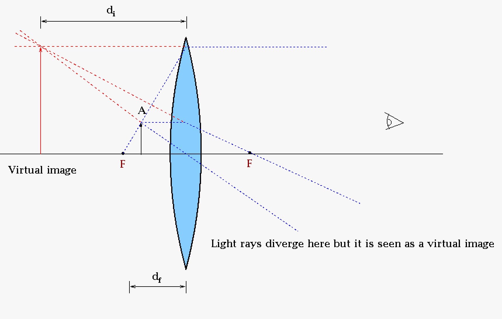 |
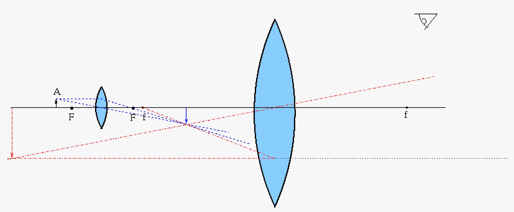
| Example of ray tracing for a converging thin lens. The real object is A at a distance \(d_o\) from the center of the lens and is represented by a line with an arrow on top. The final image is the blue line at a distance \(d_i\). Technically each part of the object line should be ray trace, but this is not necessary as each point can be determined by ray tracing the top and bottom of the object and then interpolation the rest; at least for an ideal lens. The bottom is trivial as it is the bottom of the image as well, so that just leaves the top to ray trace. The ray trace, as you can see in this cartoon, consists of three dotted lines (only two are really needed) and follow the rules that through the focal point the line bends at the lens in a "parallel" manner, a "parallel" line bends at the lens through the focal point and a ray that goes through the center of the lens does not bend. | When the object is inside the focal point we do not have a real image but a virtual image because the light rays would actual diverge, but our eyes would see an image behind the lens. The blue dotted lines represents the ray trace as we would normally do it, but since it is divergent we extend the line behind the lens with the red dotted lines. Interesting while this is a converging lens the image generation is divergent. This is how a magnifying glass normally works with the magnification being defined by \(m = \frac{d_i}{d_f}\) assuming the object is in focus. |
For telescopes, microscopes, cameras, etc. many optical elements are combined to form a whole. For an example we will look at a fairly simple microscope consisting of two converging lenses.
 |
| This is a simple cartoon of a two lens microscope. In general a real microscope would have multiple optical elements some of which will be to help the non-ideal real world issues like aberrations. |
Optical Aberrations
Above we discussed ideal mirrors and lenses but in the real world there are always aberrations because of how we need to make the optical elements3. Here we list a few of the many issues with lenses and mirrors.
| Optical Aberration | Issue | Possible resolution |
|---|---|---|
| Chromatic Aberration | Different wavelengths of light have different focal points leading to all but one wavelength slightly out of focus. | Mirrors do not have chromatic aberration, this is one of the benefits of using mirrors for telescopes. |
| Spherical Aberration | Different rays of light have different focal points in areas away from the center of the optical element; this aberration is due to the spherical nature of lenses and mirrors in the manufacturing process. | Parabolic mirrors4 and aspheric5 lenses are mostly immune to this effect. Aspheric lenses are difficult but not impossible to manufacture (mass production circa 1950s). It is possible to get the same effect as an aspheric lens with multiple "normal" lenses but it does cost in the number of optical elements and hence weight. |
| Coma | An off-axis effect that produces a tail for each optical point (looks like a comet). | Parabolic mirrors are susceptible to this when the light is not parallel. The idea of using a parabolic mirror is based off the idea that all light of the object will be parallel (theory) because the object is so far away. While this is a good assumption it is not perfect; some light will be off not parallel. This will also be a problem with lenses that are not made perfectly (not as easy as it sounds). Usually have to post-process this. |
| Astigmatism | This is where there are different focal points in different planes and essentially is a blurred image. There are two types of astigmatism the first for symmetrical optical elements and the second for non-symmetrical optical elements. | Aspheric lenses help with astigmatism, but note some systems actually employ astigmatism for their processes. Astigmatism usually is caused by defects in manufacturing. Making optical elements is not an easy process so these defects happen all the time (even for Hubble Space Telescope). |
| Field curvature | Defocusing in the radial caused by the lack of flatness in optical systems | Usually needs to be corrected post processing |
| Fringing | An interference pattern effect caused by |
Note that aberrations can be caused by a multitude of factors such after manufacturing processes and even dust, plus aberrations can be introduced when assembling a number of optical elements into an optical system. An optical engineer works to reduce these effects. This is precision work that can take quite awhile. Not everything can be solved (for instance dust, etc. that might accumulate on a telescope after assembly - even in space). So after the system is perfected by an optical engineer we move on to post processing (i.e. we let a computer correct it). Finally note this brief introduction does not take into account many other aspects of optical engineering that needs to be considered (weight of overall system, light leaks, light transmission and reflectivity, masking issues, etc.).
There are many software techniques to correct optical problems after the system is already designed and in use. Generally they depend on images taken before the system is put into use (in say a detector/optical system laboratory). Using software however is a sort of last resort method and it is best to produce the best system possible before this action is taken.
Spot Diagrams
There are many ways to characterize an optical systems. Characterizing a system would start with a spot diagram which is a very accurate ray tracing of the optical system. Aberrations can be identified in this characterization. Typically spot diagrams of standard telescopes are common place and easily found on the web. The point spread function (PSF) which is related through a Fourier transform to the optical transfer function (OTF) or real portion of the Modulation Transfer function (MTF) is an actual test of the optical system that shows how a point spreads going through the optical system. A number of software packages (Zemax, COMSOL Multiphysics, etc.) will do spot diagrams or you could write your own program.
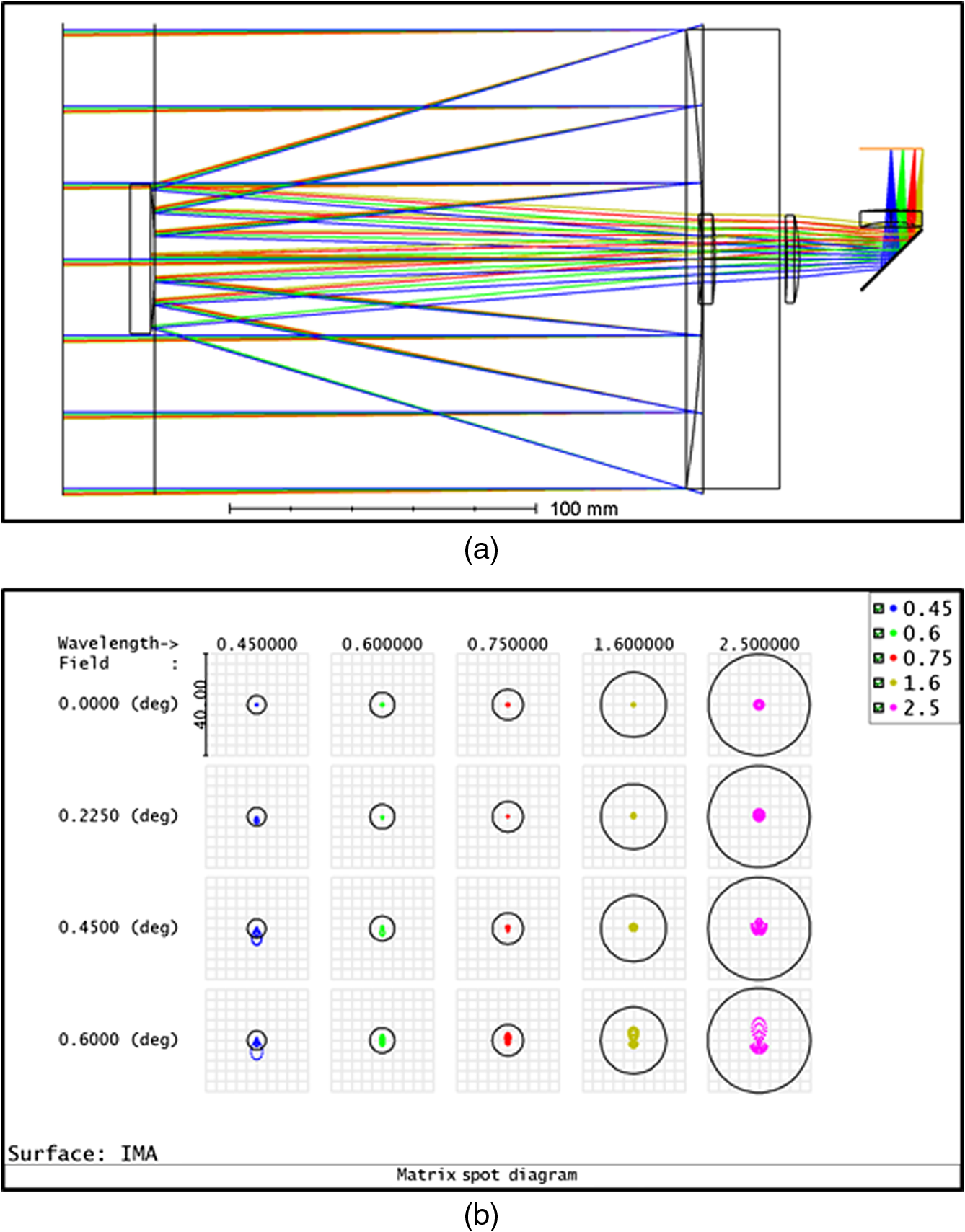 |
| Example of ray tracing and the resulting spot diagrams. Paul C. T. Rees, Ian P. Baker, David A. Thomson, Dean Catterall, Martin Coleman, Martyn L. Jones, John B. Mitchell, "Development of a lightweight camera for high altitude platform systems," Opt. Eng. 59(10) 105104 (20 October 2020) https://doi.org/10.1117/1.OE.59.10.105104. SPIE, Optical Engineering, CC by 4.0. (Assignment: Read this paper) |
Telescopes
There are many type of telescopes that have pros and cons. Engineers have to balance the pros and cons when choosing a telescope. As in other engineering systems any time you improve on aspect of your system (your telescope) you worsen another aspect of your system. Most major telescope systems are based off the Cassegrain-type reflecting telescopes. Keplerian is not favored mainly because of the weight of the lenses in large systems for these refractor telescopes.
| Keplerian | Newtonian | Cassegrain |
|---|---|---|
 |
 |
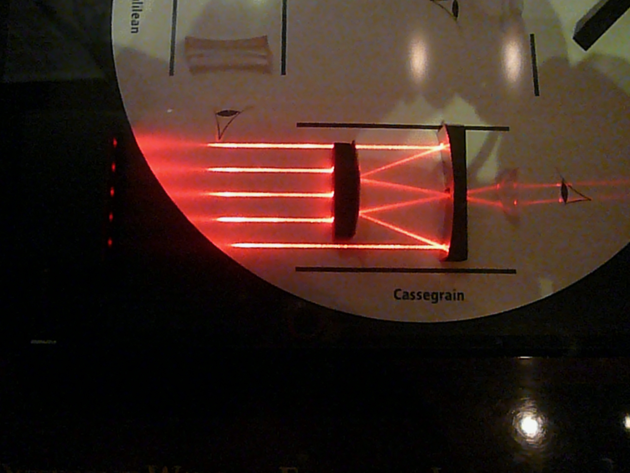 |
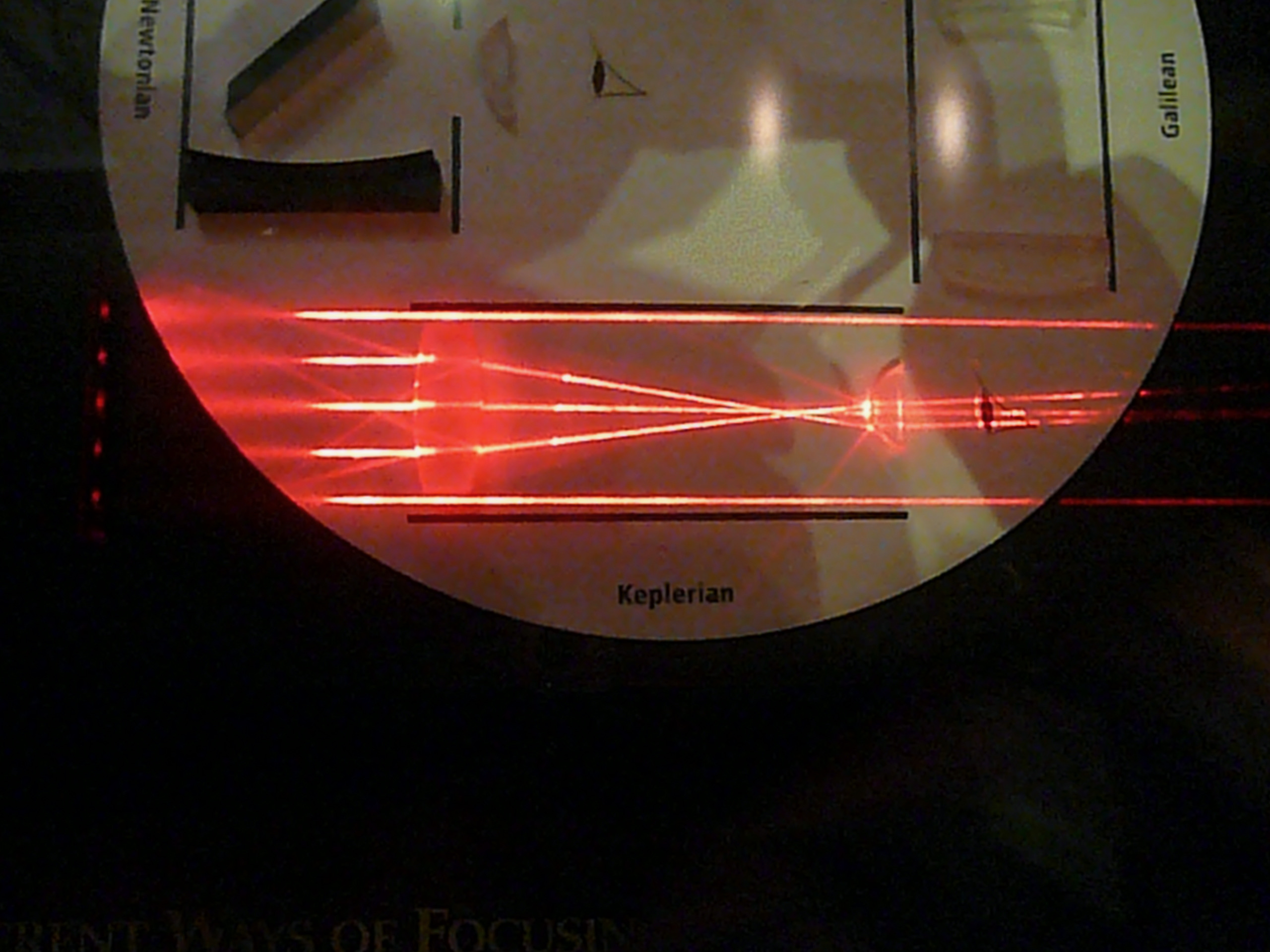
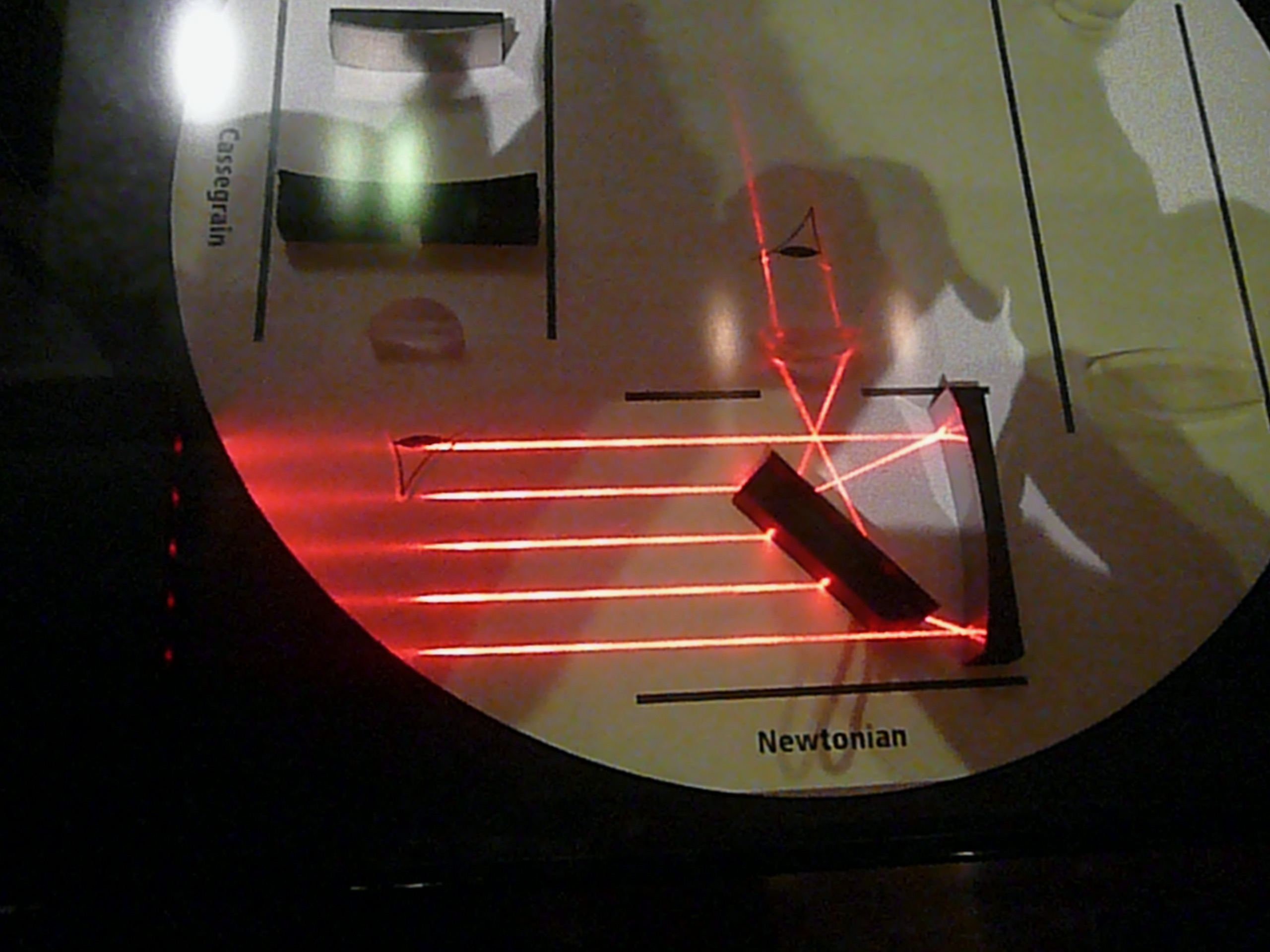
| Refractor telescope where the light comes in from the left and is viewed by your eye at the right. From this picture taken by authors at the Air & Space Museum in Washington DC you can see the parallel light from the left coming into a converging lens (where the magnified image will be formed) and going through the divergent lens . The refractor telescope's "inventor" is unknown. | Reflector telescope where the light comes in from the left and is incident on the primary mirror and reflects to a secondary mirror that reflects the image at 90 degrees to the detector (eye in this case). The Newtonian telescope is credited to Newton. | Reflector telescope where the light comes in from the left and is incident on the primary mirror and then reflected by the secondary mirror through a hole in the primary mirror and into the detector (eye in this case). The primary mirror is concave (virtual image will be magnified) and the secondary mirror is convex. |
Refractor telescope major issues
- Chromatic aberration
- Distortion on the edges
- For large telescopes very heavy (try picking up a one meter piece of glass)
- Solution
- Use a reflector telescope as they are lighter than refractors for large telescopes (try picking up a one meter thin piece of aluminum)
- Solution
- Works almost exclusively in the visual range only as most glasses do not transmit infrared (IR) and ultraviolet (UV), at least efficiently
- Solution for IR and UV
- Use mirrors which can be used for X-ray6, UV, visible, IR, and radio7.
- Use quartz, though this might be too expensive and a bit overkill as mirrors would do
- Solution for IR and UV
- Solutions for aberrations:
- Use convex lenses (Kepler)
- Use mirrors (reflecting)
Reflecting telescopes major issues
- Coma
- Spherical aberrations
- Central obstruction
- Sensitive to collimation
Types of Telescopes with notes
- Newtonian
- Cassegrain (classic version)
- To reduce spherical aberrations
- Parabolic primary
- Slightly hyperbolic secondary
- Compact
- To reduce spherical aberrations
- Schmidt-Cassegrain
- Very short, compact, and cheap
- Corrector plate to make shorter
- More coma and spherical aberration as a result
- Inexpensive especially for laypeople
- Ritchey-Chrétien
- To reduce coma
- Make the primary more hyperbolic than the classic Cassegrain
- Make the secondary more hyperbolic than the classic Cassegrain
- Specialized Cassegrain
- Hubble Space Telescope (HST)
- Advantages
- Very little coma (due to hyperbolic mirror)
- Only two surfaces (so less light loss)
- No corrector plate (refractive elements)
- Glass, etc. reduce Infrared transmission which HST needs to view
- Less light loss
- Good flat field
- Disadvantages
- Third-order coma
- Severe large-angle astigmatism (the cost for reducing coma)
- Severe field curvature
- May not be an issue if you are not try to view large fields
- Getting mostly rid of coma is more important
- Advantages
- To reduce coma
- Maksutov-Cassegrain
- Better resolution than schmidt-cassegrain, however heavier
- Nasmyth
- Gregorian
- Concave Mirror
- Usually, Earth observing though some space versions
- Dall-Kirkham
- Herschelian
- Off-axis telescope (therefore no central obstruction)
- Schiefspiegler
- Off-axis telescope (Cassegrain variant)
- Yolo
- Off-axis telescope
- Toroidal reflectors
Diffraction
Diffraction is the effect of light spreading out do to a small slit, opening, or screen. A result of these is bending of light around objects that you might otherwise think is blocking the light. This is of particular concern to low light activities like scientific observation through a telescope. We will only discuss briefly some of the ideas behind diffraction without going over the physics. Your physics and materials science will give more through discussions of this topic.
Fraunhofer
Fraunhofer diffraction happens when the light source is far8 from the slit or opening. The wave fronts are therefore planar. We see Fraunhofer diffraction from apertures9 either rectangular or circular. Circular apertures produce the well known Airy disk where the center is very bright and radially continue outwards interweaving between dark rings and every dimming light rings. The optical engineer would work to reduce this as much as possible.
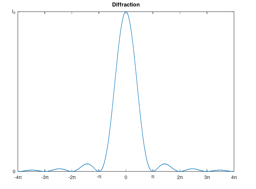 |
| The basic diffraction pattern is described by the square of the sinc function. As you will see there is at maximum initial intensity at the center and then goes from no intensity to an every small percentage of the initial intensity. Note: this graph could be viewed as a 2-D point spread function (3-D PSF would be better). |
Fresnel
Fresnel diffraction10 happens when the light source is near the slit, opening, or mask. The wave fronts are therefore spherical. Mask apertures9 can act as a Fresnel diffraction generator where the source is the edge of the mask and the opening is the gap between the mask and the detector. While this cannot be avoided totally in real systems the optical engineer would work to reduce this as much as possible.
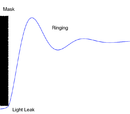 |
| Cartoon (image) of light intensity as a result of a mask. The the black rectangle represents the mask and the cartoon shows how light leaks under the mask (not related to Frensnel, just an issue for optical engineers) and the light pattern of oscillation (rings) directly after the mask ends (ringing is a term used in electrical engineering and we employ it here as well). The "ringing" is due to Fresnel diffraction. This cartoon is more dramatic then it would be in a real system for the purpose of emphasis nevertheless light leak and ringing will be observed in any masked system. |
The previous discussion is just a brief taste of some of the issues the an optical engineer may encounter with diffraction.
Polarization
Polarization of light11 describes how their the electric field and magnetic field oscillate. Polarization can be linear or circular with circular (or elliptical) being subdivided into right and left circular polarization. Unpolarized light is a mix of all the various polarization. Results of polarization in certain materials (plastics) can be used to measure stress in objects which would be useful to engineers. For science polarized waves indicate directional12 information that give further detail of an event or object.
Some materials index of refraction are dependent on polarization (among other dependencies) and these materials are call birefringent. A number of optical systems use birefringence.
The next topic is a brief discussion of chemistry which is mostly covered in the other Libretexts course associated with this course.
1Also known as Descartes' law in France because Rene Descartes independently described refraction and reflection (though he assumed the speed of light was infinite). The description of reflection and refraction has a long history and includes Ptolemy, Ibn Sahl (who greatly extend the work of Ptolemy), and other polymaths. Assigning a name to these laws is just a convention and does not accurately acknowledge the work of many scientists and engineers.
2Principle of least action as described by the Hamilton's principle. Note that Fermat's proof did not assume an infinite speed of light but a finite speed of light.
3The most obvious issue would be with lenses that are not really infinitely thin, but have a thick part in the center and become thinner as they go to the ends.
4For very high end telescopes for astronomical observation the "fast" or low f ratio requires the parabolic mirror to be more hyperbolic (how much? well that is a complex design issue and is why we have optical engineers.).
5The aspheric lens design takes standard shape of a lens and reshapes it at the ends. This needs to take into account the index of refraction of the material and then design the surface to be more hyperbolic in looks.
6X-rays have to have mirrors designed to have the light graze on multiple mirrors as the energy is very strong and would rip through they mirror if it was head-on with a. Gamma rays' energy is too powerful for mirrors and are usually capture through a crystal's reaction to the ray.
7Radio uses parabolic steel or mesh structures that acts exactly like a mirror so we believe you could still define that as a mirror.
8Technically it a function of distance, width of opening, and wavelength, but we will assume that some standard design standards are employed such that really only distance is an issue here (fully study of optics should include all factors).
9Apertures are used to reduce the amount of light coming into a system in order to prevent saturation of detectors. Sometimes an aperture is used as a mask unwanted light signals impinging on the detector (sometimes in places that are meant to be dark but can detect light themselves).
10Just like Fraunhofer, Fresnel is also a function of distance, width of opening, and wavelength, but we will only look at one aspect of Fresnel diffraction as we present just some tidbits for interest not an optics course. Technically diffraction for very near light sources is Kirchhoff diffraction defined by the Kirchhoff-Fresnel equations but that is too far off topic at this point of your academic career.
11Light waves are transverse waves as opposed to pressure or sound waves with are longitudinal waves.
12Symmetry (is something asymmetric or symmetric)