
1.2: Lévy-Mises Equations
- Page ID
- 7780
")
Once the yield criterion is satisfied, we can no longer expect to use the equations of elasticity. We must develop a theory to predict plastic strains from the imposed stresses.
When a body is subjected to stresses of sufficient magnitude, it will plastically deform (or fracture). The nature of the stresses depend on the particular forces applied to the body and, often, the same resulting deformation may be achieved by applying forces in different ways. For instance, a ductile metallic rod may be extended (elongated) a given amount either by a single force along its axis (i.e. a tensile stress) or by the combined action of several forces acting in different directions (i.e. multi-axial loading). A simple example of the latter multi-axial loading situation to obtain the same extension in the metallic rod as that obtained in pure tension is to apply a reduced tensile stress while simultaneously compressing the rod along its length. Under such multi-axial loading, the behaviour of ductile metallic materials can be described by the Lévy-Mises equations, which relate the principal components of strain increments during plastic deformation to the principal applied stresses.
In general, there will be both plastic (non-recoverable) and elastic (recoverable) strains.
However, to a first approximation, we can ignore the elastic strain assuming that the plastic strains will dominate in a deformation processing situation. We can therefore treat the material as a rigid-plastic, i.e. a material which is perfectly rigid prior to yielding and perfectly plastic afterwards.
Since plasticity is a form of flow, we can relate the strain rate, \( \dfrac{\mathrm{d} \varepsilon}{\mathrm{dt}} \) to stress σ.
Plastic flow is similar to fluid flow, except that any rate of flow (strain rate) can occur for the same yield stress.
From symmetry we can show that in an isotropic body, the principal axes of stress and strain rate coincide, i.e. it goes the way you push it.
With respect to principal axes
\[ \frac{\dot{\varepsilon}_{1}}{\sigma^{\prime}_{1}}=\frac{\dot{\varepsilon}_{2}}{\sigma^{\prime}_{2}}=\frac{\dot{\varepsilon}_{3}}{\sigma^{\prime}_3} \],
where \( \dot{\varepsilon}_{i}=\dfrac{\mathrm{d} \varepsilon}{\mathrm{dt}}(i=1,3) \), the normal strain rate parallel to ith axis.
\( \sigma_{i}^{\prime} \) = deviatoric component of normal stress parallel to the ith axis, and
\[ \sigma_{1}^{\prime}=\sigma_{1}-\frac{1}{3}\left(\sigma_{1}+\sigma_{2}+\sigma_{3}\right) \]
If we consider small intervals of time δt, and call the resultant changes in strain δε1, δε2, δε3, it follows that,
\[ \frac{\delta \varepsilon_{1}}{\sigma_{1}-\frac{1}{2}\left(\sigma_{2}+\sigma_{3}\right)}=\frac{\delta \varepsilon_{2}}{\sigma_{2}-\frac{1}{2}\left(\sigma_{3}+\sigma_{1}\right)}=\frac{\delta \varepsilon_{3}}{\sigma_{3}-\frac{1}{2}\left(\sigma_{1}+\sigma_{2}\right)} \] the Lévy-Mises equations.
As \( \frac{1}{3}\left(\sigma_{1}+\sigma_{2}+\sigma_{3}\right) \) is an invariant of the stress tensor, it also turns out that these equations apply even if stresses and strains are not referred to principal axes, so
\[ \frac{\delta \varepsilon_{11}}{\sigma_{11}-\frac{1}{2}\left(\sigma_{22}+\sigma_{33}\right)}=\frac{\delta \varepsilon_{22}}{\sigma_{22}-\frac{1}{2}\left(\sigma_{33}+\sigma_{11}\right)}=\frac{\delta \varepsilon_{33}}{\sigma_{33}-\frac{1}{2}\left(\sigma_{11}+\sigma_{22}\right)} \]
for a general stress tensor and plastic strain increments δε11, δε22 and δε33.
The above Lévy-Mises equations describe precisely the relationships between the normal stresses (arising from any general applied stress situation with respect to a particular set of orthogonal axes) and the resulting normal plastic strains (deformation) of a body referred to the same set of orthogonal axes. In many situations, the precise stresses are not known accurately and so more empirical approaches can be very helpful in describing the deformation of a body when subjected to applied forces. A number of these approaches are considered in this TLP. However, several require further constraints, in particular the need to work in two dimensions and this introduces the concepts of plane stress and plane strain.
Plane Stress
In plane stress, one of the principal stresses is zero but there are three finite strains. An example of this is the surface of a thin walled, pressurized cylinder, where the principal stress normal to the surface has a value of zero. More generally, plane stress conditions occur in sheet metal forming when a thin sheet is subjected to uniaxial or biaxial tension.
Plastic Deformation in Plane Stress
Consider the uniaxial tensile behavior of a sheet (Figure \(\PageIndex{1}\)).
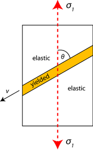
Figure \(\PageIndex{1}\): Uniaxial Tensile Behavior of a Sheet
Plastic flow will result once a critical stress is reached. Due to the constraint of neighboring elastic material, the plastically deforming material forms in a band across the sheet at a characteristic angle to the axis of loading.
\[ \sigma_{1} \neq 0, \sigma_{2}=\sigma_{3}=0 \]
At the boundary between the elastic and the yielded material, longitudinal strains must match for continuity. Therefore, they must be zero since strain is effectively zero in the elastic regions.
Plastic strain along v is zero: \( \delta \varepsilon_{v v}=0 \)
From the Levy-Mises equations
\[ \dfrac{\delta \varepsilon_{1}}{\sigma_{1}}=\dfrac{\delta \varepsilon_{2}}{-1 / 2 \sigma_{1}}=\frac{\delta \varepsilon_{3}}{-1 / 2 \sigma_{1}} \]
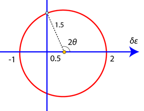
and so \( \delta \varepsilon_{1}=-2 \delta \varepsilon_{2} \) in the plane of the sheet.
Hence if we let \( \delta \varepsilon_{1}=+2 \) units of plastic strain,
\( \delta \varepsilon_{2}=-1 \) unit of plastic strain.
Therefore, on a Mohr's circle, we have:
and the longitudinal strain \( \delta \varepsilon \) is zero, i.e. \( \delta \varepsilon_{v v}=0 \), at an angle \(θ\) with respect to the direction parallel to \(σ_1\).
From the diagram,
\[ \begin{array}{l}{\cos (180-2 \theta)=\dfrac{0.5}{1.5}=\dfrac{1}{3}} \\ {\Rightarrow \theta=1 / 2 \cos ^{-1}(-1 / 3)=54.74^{\circ}}\end{array} \]
and so the longitudinal strain increment is \( \delta \varepsilon_{v v}=0 \)at an angle of with respect to \(σ_1\).
This phenomenon is well known in mild steel (Figure \(\PageIndex{2}\)). The bands created are known as Lüders bands. These bands require less stress for their propagation than for their formation because of the freeing of dislocations from their solute atmospheres.
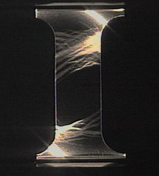
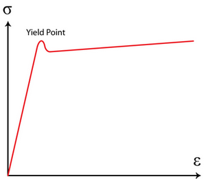
Figure \(\PageIndex{2}\): Lüders bands formation in steel, contributed by Mike Meier, University of California, Davis.
It is worth noting that Lüders bands occur in certain types of steel, such as low carbon steel (mild steel), but not in other metallic alloys, such as aluminum alloys or titanium alloys. This is because plastic strain localization is normally suppressed by work hardening, which tends to make plastic flow occur rather uniformly in a metal, particularly in the early stages of plastic flow, i.e., just after yield has taken place.
However, in certain types of low carbon steel at room temperature, Cottrell atmospheres of carbon atoms which have been able to segregate preferentially to dislocation cores pin dislocations until the upper yield point is reached. Once the upper yield point is reached, there is a load drop and then a sudden burst of plastic straining at a constant externally applied load, as cascades of dislocations are able escape their Cottrell atmospheres. This is clearly rather specialized behavior, caused by the ability of carbon atoms to diffuse relatively easily interstitially in these steels, but it is actually necessary behavior for the formation of Lüders bands.
Conventional work hardening in metallic alloys in the early stages of plastic deformation makes any strain localization (as demonstrated by the formation of Lüders bands) unlikely. This is also the case for pure metals, and for metals at high temperature, where large plastic strains can occur without a significant load increase once plastic deformation begins.
Therefore, Lüders bands only form if a limited burst of plastic straining is able to take place at constant load. Mild steels heated to sufficiently high temperatures (> 400 °C) and then tensile tested do not exhibit Lüders bands.
Plane Strain
Much deformation of practical interest occurs under a condition that is nearly, if not exactly, one of plane strain, i.e. where one principal strain (say ε3) is zero so that δε3=0.
Plane strain is applicable to rolling, drawing and forging where flow in a particular direction is constrained by the geometry of the machinery, e.g. a well-lubricated die wall. A specific example of this is in rolling, where the major deformation occurs perpendicular to the roll axis. The material becomes thinner and longer but not wider. Frictional stresses parallel to the rolls (i.e. in the width direction) prevent deformation in this direction and hence a plane strain condition is produced where \( \delta \varepsilon_{3}=0 \). This can be seen in the animation below.
HOT ROLLING
Reproduced from Materials Selection and Processing CD, by A.M.Lovatt, H.R.Shercliff and P.J.Withers.
Plastic deformation in plane strain
Here, one principal strain is zero. Let this be ε3. Then \( \delta \varepsilon_{3}=0 \).
From the Levy-Mises equation,
\[ \frac{\delta \varepsilon_{1}}{\sigma_{1}-\frac{1}{2}\left(\sigma_{2}+\sigma_{3}\right)}=\frac{\delta \varepsilon_{2}}{\sigma_{2}-\frac{1}{2}\left(\sigma_{3}+\sigma_{1}\right)}=\frac{\delta \varepsilon_{3}}{\sigma_{3}-\frac{1}{2}\left(\sigma_{1}+\sigma_{2}\right)} \neq 0 \]
it follows that \( \sigma_{3}=\frac{1}{2}\left(\sigma_{1}+\sigma_{2}\right) \) in order to avoid \( \dfrac{\delta \varepsilon_{1}}{\sigma_{1}-\frac{1}{2}\left(\sigma_{2}+\sigma_{3}\right)}=0 \)
Hence σ3 is the mean of σ1 and σ2. By convention we define σ1 > σ2 σ1 > σ3 > σ2. Therefore the maximum shear stress in the σ1- σ2 plane is at 45° to the axes and has magnitude σ1−σ22 .
If we now examine the Tresca and von Mises yield criteria, we find:
- Tresca \( \frac{\sigma_{1}-\sigma_{2}}{2}=k=\frac{Y}{2} \) (\(k\) = shear yield stress and \(Y \) = uniaxial yield stress)
- von Mises \( \left(\sigma_{1}-\sigma_{2}\right)^{2}+\left(\sigma_{2}-\sigma_{3}\right)^{2}+\left(\sigma_{3}-\sigma_{1}\right)^{2}=6 k^{2}=2 Y^{2} \)
If
\[ \sigma_{3}=\frac{1}{2}\left(\sigma_{1}+\sigma_{2}\right), \frac{3}{2}\left(\sigma_{1}-\sigma_{2}\right)^{2}=6 k^{2}=2 Y^{2} \]
then
\[ \left(\sigma_{1}-\sigma_{2}\right)=2 k=\frac{2 Y}{\sqrt{3}} .\]
Therefore, if we have plane strain, the Tresca yield criterion and the von Mises yield criterion have the same result expressed in terms of \(k\). It is unnecessary to specify which criterion we are using, provided we use \(k\).
Note
Consider a metal in uniaxial compression where plastic strain only takes place in the 1-2 plane. There is no friction between the work piece and the die faces. (To achieve this experimentally, a sample should be wide in the 3 direction).
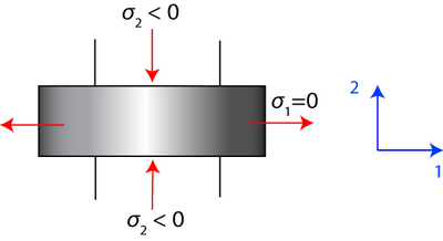
\[ \Rightarrow \sigma_{\mathrm{ij}}=\left( \begin{array}{ccc}{\sigma_{1}} & {0} & {0} \\ {0} & {\sigma_{2}} & {0} \\ {0} & {0} & {\frac{\sigma_{1}+\sigma_{2}}{2}}\end{array}\right) \nonumber \]
Hydrostatic stress:
\[ \sigma_{H}=-p=\frac{\sigma_{1}+\sigma_{2}}{2}=\sigma_{3} \]
where p is the hydrostatic pressure.
So at yield, we have \( \frac{\sigma_{1}-\sigma_{2}}{2}=k \) and since \( \frac{\sigma_{1}+\sigma_{2}}{2}=-p \), we have
\[ \sigma_{1}=-p+k=0 \]
\[ \sigma_{2}=-p-k=-2 k \]
since \(p=k\) at yield
\[ \sigma_{3}=-p \]
So for this example, the stress tensor is
\[ \sigma_{\mathrm{ij}}=\left( \begin{array}{ccc}{-p} & {0} & {0} \\ {0} & {-p} & {0} \\ {0} & {0} & {-p}\end{array}\right)+\left( \begin{array}{ccc}{k} & {0} & {0} \\ {0} & {-k} & {0} \\ {0} & {0} & {0}\end{array}\right) \]
which is the sum of hydrostatic stress (which can vary in magnitude through the object) and deviatoric pure shear stress (which has the same value throughout the material).
The directions of maximum shear therefore lie at 45° to σ1 and σ2. These are slip lines along which plastic flow occurs.
We are avoiding additional complexities such as work hardening by assuming the materials are rigid-plastic.