
7.5: Beam deflections from applied bending moments
- Page ID
- 7825
")
he second derivative (curvature) of the neutral axis line (dotted line in diagram)
\[\kappa=\frac{d^{2} y}{d x^{2}}\]
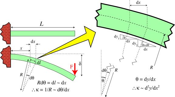
The approximation involved in equating beam curvature to the curvature of the neutral axis of a beam.
It follows that
\[M=\kappa E I=E I \frac{\mathrm{d}^{2} y}{\mathrm{d} x^{2}}\]
Since the moment at the section concerned can also be written, for a cantilever beam, as M = F (L - x)
it follows that
\[E I \frac{\mathrm{d}^{2} y}{\mathrm{d} x^{2}}=F(L-x)\]
This second order differential equation can be integrated (twice), with appropriate boundary conditions, to find the deflection of the beam at different points along its length. For a cantilever beam, this operation is shown below.
\[E I \frac{\mathrm{d} y}{\mathrm{d} x}=F L x-\frac{F x^{2}}{2}+C_{1}\]
\(\text { at } x=0, \frac{\mathrm{d} y}{\mathrm{d} x}=0, \text { thus } C_{1}=0\)
\[E I y=\frac{F L x^{2}}{2}-\frac{F x^{3}}{6}+C_{2}\]
\(\text { at } x=0, y=0, \text { thus } C_{2}=0\)
which can be rearranged to give
\[y=\frac{F x^{2}}{6 E I}(3 L-x)\]
For example, at the loaded end ( x = L ), this gives
\[\delta=\frac{F L^{3}}{3 E I}\]
Symmetrical 3-point bending
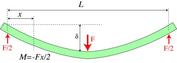
Symmetrical 3-point bend loading
The bending moment is given by
\[M=\frac{-F x}{2}\]
It follows that
\[E I \frac{\mathrm{d}^{2} y}{\mathrm{d} x^{2}}=\frac{-F x}{2}\]
and the integration procedures lead to
\[E I \frac{\mathrm{d} y}{\mathrm{d} x}=-\frac{F x^{2}}{4}+C_{1}\]
\(\text { at } x=\frac{L}{2}, \quad \frac{d y}{d x}=0 \text { thus } C_{1}=\frac{F L^{2}}{16}\)
\[E I y=\frac{-F x^{3}}{12}-\frac{F L^{2} x}{16}+C_{2}\]
\(\text { at } x=0, y=0 \text { thus } C_{2}=0\)
so the equation for the deflection is
\[y=\frac{F x}{48 E I}\left(3 L^{2}-4 x^{2}\right)\]
and deflection of the centre of the beam is given by
\[\delta=\frac{F L^{3}}{48 E I}\]