
7.7: Springs
- Page ID
- 21415
")
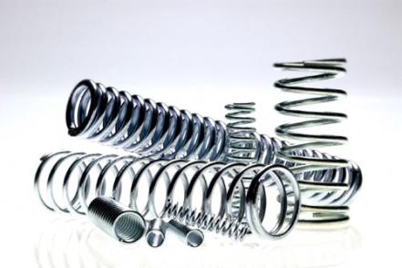
A collection of assorted springs
An interesting example of torsion is provided by the deformation that takes place during the loading of springs (torsional coils). Of course, these have a wide range of engineering applications. They are normally made of (high yield stress) metals. (Ceramics are too brittle, while polymers are insufficiently stiff: fibre composites are also unsuitable - see below.) When a spring is loaded (compressed or extended), the deformation experienced by the wire is one of pure torsion. This is illustrated in the diagram below.
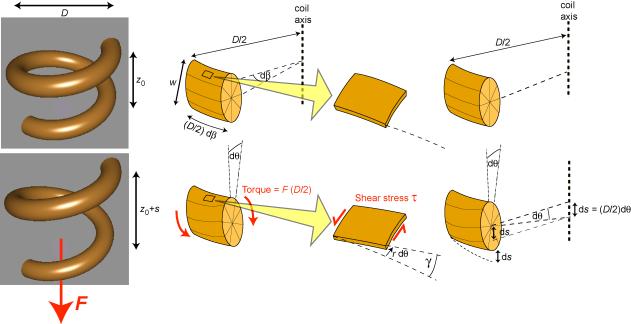
Illustration of how the application of an axial load, F, to a spring generates torsional deformation of the wire and hence axial extension of the spring.
The torque acting on the wire is given by
\[T=F\left(\frac{D}{2}\right)\]
in which F is the axial force and D is the coil diameter. It can be shown in the example below that the shear stress within the wire (at a distance r from the core) is given by
\[\tau=\frac{T r}{2 I}\]
in which I is the bending second moment of area (NOT the polar moment), and the shear strain in the wire is related to the change in axial extension of one turn of the coil, s , by the expression
\[\gamma=\frac{2 s r}{\pi D^{2}}\]
Measurement of the extension (per turn) of a spring, as a function of the applied force (first carried out systematically by Robert Hooke , in his pioneering work on the nature of elasticity) is a very convenient method of obtaining elastic constants. The ratio of τ to γ , obtained from the above equations, gives the shear modulus, G . The loading geometry is such that a large axial extension (per turn) is generated, while the strains within the material remain low, particularly for springs with a large ratio of D to w . Of course, this is exactly why springs are of practical use - they accommodate large deflections or displacements without the material being strained beyond its elastic limit (which is small for all materials except rubbers).
It's interesting to note why springs are not normally made of fibre composites. The natural orientation for the fibres would be along the length of the rod (wire) to be formed into a coil. However, these fibres would have very little effect on the shear modulus in a transverse section of the rod, which is the property that controls the elastic extensions of the spring. It might as well have been made solely of the polymeric matrix (although such springs have a very low stiffness). It's only by winding fibres into the hoop direction of the rod that the shear stiffness of transverse sections would be boosted. However, this is impractical, at least for anything but very large scale springs, since it would require the fibres to adopt higher curvatures than would normally be possible.
Example \(\PageIndex{1}\)
Consider the small elemental length of the wire shown in the figure, subtending an angle dβ at the axis of the coil. The torsional shear stress within the wire, τ, can be found by noting that it varies linearly with distance from the centre of the wire ( τ = κ r , where κ is an unknown constant and r is the distance of the element from the centre of the wire) . The torque can now be expressed in terms of internal forces in the wire. The force in an individual element of the wire is given by the torsional shear stress, τ, multiplied by the area of the element, 2 π r dr . Therefore, the elemental torque is simply this force multiplied by the distance of the element from the neutral axis of the wire, r . Summation of these elemental torques gives the total torque:
\[T=\int_{0}^{w / 2} \tau(2 \pi r \mathrm{d} r) r=2 \pi K \int_{0}^{w / 2} r^{3} \mathrm{d} r=\frac{\pi}{32} K w^{4}\]
\[\tau=K r=\frac{32 T r}{\pi w^{4}}=\frac{T r}{2 I}\]
where I is the second moment of area for a solid cylinder (the wire), given by:
\[I=\frac{\pi w^{4}}{64}\]
The local shear strain in the material is given by
\[\gamma=r \frac{\mathrm{d} \theta}{\mathrm{d} L}=\frac{r \mathrm{d} \theta}{(D / 2) \mathrm{d} \beta}\]
in which dθ /dL is the rate of twist along the length of the wire. The incremental angle of twist of the wire is therefore related to the corresponding incremental rotation angle of the coil by
\[\mathrm{d} \theta=\gamma \frac{(D / 2)}{r} \mathrm{d} \beta\]
The axial displacement of the coil, due to the twisting of the elemental section, can therefore be written
\[\mathrm{d} s=\left(\frac{D}{2}\right) \mathrm{d} \theta=\left(\frac{D}{2}\right) \gamma\left(\frac{D}{2 r}\right) \mathrm{d} \beta\]
The axial displacement associated with the twist in one complete turn of the coil is thus
s=\left(\frac{D^{2}}{4 r}\right) \gamma \int_{0}^{2 \pi} \mathrm{d} \beta=\frac{\pi D^{2}}{2 r} \gamma
The local shear strain in the wire is therefore related to the increase in spacing between adjacent turns in the coil by
\[\gamma=\frac{2 s r}{\pi D^{2}}\]