
12.5: Multiaxial Creep Testing – The Creeping Coil
- Page ID
- 7861
")
Background
Note: this experiment deals with torsion which can be explored further in the Bending and Torsion of Beams TLP here
This experiment is a simple and convenient one to carry out. The sample is in the form of a wire that is wound into a coil, which creeps under its own weight. Using a low melting point material such as lead or solder, this occurs at relatively low temperatures (without heating, or using a simple hot air system). Several simplifying assumptions are made in carrying out the analysis. Each turn of the coil is taken to experience a constant stress - the average value acting throughout the section of the wire. Furthermore, it is assumed that the steady state regime of behaviour is immediately established everywhere - ie primary creep is neglected. These are crude assumptions and the experiment cannot be used to obtain quantitative creep characteristics. However, it is possible to obtain fairly reliable indications of the dependence of creep rates on temperature (ie values of Q) and, to some extent, on stress (ie values of n)
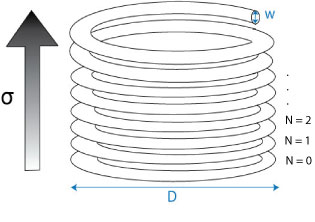
Diagram showing the coil with each turn assigned a number starting from N=0 when the stress is zero
The stress in a particular turn is proportional to its number, N, where the turns are numbered beginning from zero at the bottom turn and ending at the top. The shear stress in each turn varies from zero at the centre of the turning to a maximum value at the edge of the coil and it’s average, τ, is given by:
\[\tau=B N\]
where B is a constant of proportionality (for this experiment). The coil is then allowed to creep over a fixed amount of time (e.g. one minute) and at the end of this time the spacings, s, between the turns are measured.The average local shear strain γ in each turn is a function of s and is given by
\[\gamma=C s\]
where C is a constant. Assuming that steady state creep dominates, the strain rate is simply the strain divided by the time. This equation can now be used to explore the relationship between strain rate and shear stress
\[\dot{\gamma}=C \frac{s}{t}\]
Using the steady state creep equation:
\[\dot{\gamma}=A \tau^{n} \exp \left(-\frac{Q}{R T}\right)\]
Taking natural logarithms:
\[\ln \dot{\gamma}=\ln (A)+n \ln (\tau)-\frac{Q}{R T}\]
using the expressions for average shear stress and average strain rate:
\[\ln \left(\frac{s}{t}\right)=K+n \ln (N)-\frac{Q}{R T}\]
where
\[K=\ln (A)+n \ln (B)-\ln (C)\]
This equation can be used to evaluate the creep parameters from (plots of) experimental data.
Experimental Set-Up
https://www.doitpoms.ac.uk/tlplib/creep/videos/28.mp4
https://www.doitpoms.ac.uk/tlplib/creep/videos/85.mp4
In order to create a temperature-controlled environment, the coil is placed inside a Perspex tube. Once the temperature in the tube has stabilised, the coil is allowed to creep under its own weight for one minute. The videos above show qualitatively how creep rate varies with temperature.
Evaluating Parameters
The spacings between the turns of the coil can be obtained from photos or more simply by just rotating the support cylinder until it is horizontal (so that creep will stop). Spacings are then readily measured directly with a ruler. The spacing of the Nth turn is taken as the distance between the Nth and (N-1)th turn, i.e. the spacing of the 1st turn is the distance between the 0th and 1st turn. Using the equation above marked with an asterisk, a plot can be constructed of ln(s/t against ln N), at a given temperature, with the stress exponent, n, obtainable from the gradient. A similar operation can be carried out using data for a number of different temperatures, with ln(s/t) plotted against 1/T, for a selected value of N, to obtain the activation energy, Q