21.3: Processing before recycling
- Page ID
- 43529
Metals are used in a wide variety of applications. They will therefore be in a wide variety of states when they are sent for recycling.
Sorting and processing of metal scrap is essential, because when melted, mixtures of metals may become alloys. Without careful separation the quality of the final product will be reduced. This issue is explored and explained later in this TLP.
In this section, four examples of sorting and processing are investigated:
- the Eddy current separation method (electromagnetic induction)
- the leaching and electrolysis of tin from steel cans (electrochemistry)
- the theoretical cryogenic separation of copper from steel motors (ductile-brittle transition)
- the chemical oxidation of tramp elements from molten steel scrap (Ellingham diagram)
Phase diagrams are also used to illustrate the problems that can occur when not all contaminants are removed.
Physical Sorting – The Eddy current separation method
The most obvious example of sorting is that of using magnets to attract ferrous scrap. Magnetism occurs in iron due to unpaired electrons in the d-orbital giving each iron atom a magnetic moment. All these moments are aligned due to the interaction of the d-orbitals, giving an overall magnetic orientation. Magnetic materials can therefore be separated easily.
A large number of materials are not magnetic - aluminium, for example. They still need to be separated before recycling.
The eddy current separation method usually sorts this non-ferrous scrap. Eddy current separation takes the principles of electromagnetic induction in conducting materials, to separate non-ferrous metals by their different electric conductivities.
The main principle is that ‘an electrical charge is induced into a conductor by changes in magnetic flux cutting through it’. Moving permanent magnets passing a conductor generates the change in magnetic flux.
Electromagnetic induction and Eddy current generation will not be explored further here (although there are links in the Going Further section if you wish to find out more about this subject). Faraday’s law (electromagnetic) describes the generation of swirling currents in conductors, such as the non-ferrous metals in this example. Swirling currents create a magnetic field in accordance with Lenz’s law that will act to oppose the change in magnetic field being applied.
The basic set up is to have the non-ferrous scrap on a conveyor belt. The conveyor passes a rotating drum, inside of which is a much faster rotating magnet block (up to 4000 rpm). The magnet block causes the changing magnetic flux. Try the interactive demonstration below!
When the conducting particles move through this changing flux on the conveyor, a spiralling current and resulting magnetic field are induced. This magnetic field of the metal particles interacts with the magnetic field of the rotating drum. The interaction gives the particles kinetic energy. The scrap particles are thrown off the end of the conveyor with varying energies, causing different trajectories depending on the conductivity of the particle.
The size of the particle and the direction of rotation of the drum can be changed to vary the degree of separation. Small particles (10–50mm) can be separated owing to the degree of electrical conductivity . The most conductive materials interact the most with the magnetic field and have the longest trajectories. Aluminium has the highest conductivity for a given weight at ambient temperature than any other element. Non-metallic elements such as plastic labels and paint do not interact with the magnetic field at all. They simply fall off the end of the conveyor belt with no change in energy.
The eddy current separator is another excellent example of how knowledge of materials properties (electrical conductivity and density ) has improved recycling technology.
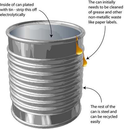
However, further processing is still needed to remove coatings and some alloys before re-melting, for example the tin coating on tin cans.
Tin Can Processing
Leaching and electrolysis of tin from steel cans
How do you remove the tin-plating from tin cans without dissolving the steel underneath? Solving this problem requires knowledge of the way in which metals corrode – an important concept in materials science.
The process is a little different today than explained here because the tin coating has been thinned (those who remember may have noticed the decreasing weight of ‘tin cans’ over the years).
The original method to remove tin from cans was stripping by electrolysis. Knowledge of electrochemistry is critical in the designing of this process. The tin plating must be removed without dissolving the steel underneath.

The reactions used
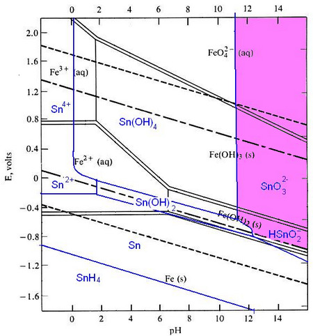
Pourbaix diagrams plot potential vs. pH. They describe the thermodynamic stability of metals that have oxidised components, as a function of the pH of the aqueous solution. Using these diagrams the most commonly used method for detinning steel has been designed.

The Pourbaix diagrams for iron (black) and tin (blue) superimposed.
At a high pH (>12) – the purple region in the diagram - Sn can be stabilised in alkali solution as HSnO–2 and as SnO2–3 in the presence of an oxidant. In this region of the diagram, iron is passivated and does not corrode. The oxidant helps this passivation to occur. In this way the tin can be removed from the surface of the can, while the steel is not harmed.
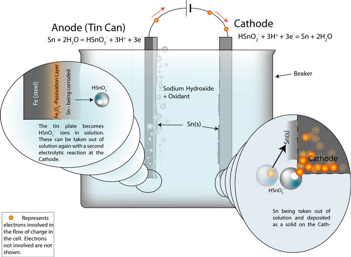
The electrochemical oxidation of the tin can be expressed as:
Sn(s) + 2H2O(l) = HSnO–2 (aq) + 3H+ + 3e- (reaction 1)
Using the Nernst equation:
\[E_{\mathrm{rev}}=E^{0}+\frac{R T}{6 F} \ln \alpha\]
We can write the electrode potential of this reaction as:
For a pH of 12 and [ HSnO–2 ] of 10-2 mol, E = –0.79V. By convention this is expressed as the reduction potential, i.e. for the reverse of reaction (1). For the tin being dissolved, the potential is reverse in sign, i.e. E = +0.79V.
Under oxidising conditions, HSnO–2 can be oxidised further to SnO2–3:
HSnO–2 + H2O = SnO2–3 (aq) + 3H+ + 2e- (reaction 2)
The Nernst potential for this is calculated:
\[E(V)=0.374-0.0886 p H+0.0295 \log \left(\frac{\left[\mathrm{SnO}_{3}^{2-}\right]}{\left[\mathrm{HSnO}_{2}^{-}\right]}\right)\]
For pH = 12 and [ SnO2–3 ] = [ HSnO–2 ] = 10-2 mol, we find that E(v) = –0.69V.
This too is a reduction potential, i.e. for the reverse of Reaction 2. The potential for turning HSnO–2 into SnO2–3 is +0.69V.

Setting up the process
An electrochemical detinning cell is arranged with the tin plated can as the anode. If the cell is arranged so that the reactions go backwards at a cathode plate, pure tin is deposited on the cathode.
Thus the overall cell reaction is Sn (anode)![]() Sn (cathode).
Sn (cathode).
The whole cell electrode potential is zero. The applied potential is not zero, because we need to put some energy in to overcome these energy barriers:
- Ohmic losses – the electrolyte, the connecting wires and the electrodes have electrical resistance.
- polarisation losses – the surfaces of the electrodes become charged and we need to supply the ions with enough energy to escape the charged layer.
In the same way as the aluminium cell, the whole cell electrode potential can be written as:
Ecell = Erev + ηA + ηC + (I · R)
where I is the current, R is the resistance of the components and ηA is the potential across the charged layer at the anode (and similar for the cathode).
The effect on the iron
At pH 12 and under oxidising conditions, the iron is passivated. Fe3O4 and/or Fe2O3 form an adherent, non-porous layer on the surface (a passivation layer). This slows down the rate of movement of Fe ions into solution and protects the iron from being dissolved. The presence of oxidising agents such as sodium nitrite makes the passivating layer form faster and more completely.
The passivation reaction producing Fe3O4 can be written as:
3Fe + 4H2O → Fe3O4 + 8H+ + 8e-
with a potential E0 = -0.085 - 0.0591 pH
Under oxidizing conditions, the passivating layer is Fe2O3:
2Fe3O4 + H2O → 3Fe2O3 + 2H+ + 2e-
with potential E0 =-0.221 - 0.0591 pH
At very high pH (>13), solutions can be corrosive to Fe, especially if they are free of oxidizing agents:
Fe + H2O → HFeO-2 + 3H+ + 2e-
E0 = -0.2493 - 0.886 pH + 0.295 log [HFeO2-]
HFeO-2 dissolves in the electrolyte and the steel can corrodes away.
The detinning process can be recreated in miniature in the laboratory:
Copper in motors
Automobiles today contain many motorised components: windows, seats, CD drives… you name it, it’s motorised. These motors contain lots of valuable copper. To take each motor apart and extract the components is not economically viable, taking into account the energy already expended in dismantling the automobile itself.
However, materials science could provide an answer:-
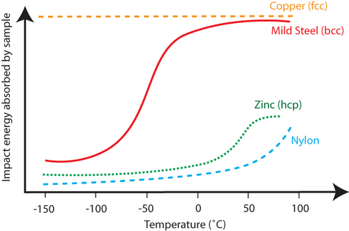
At low temperatures, materials become more brittle . This is because the movement of dislocations that enable plastic deformation is reduced at cold temperatures. There is a difference in the crystal structures of copper and the other components of the motor (steel and polymers). Copper has a face-centred-cubic (fcc ) structure (also known as cubic close packed), and steel has a body-centred-cubic (bcc ) structure. The fcc crystal structure has more slip systems on which dislocations can move than the bcc crystal structure. Copper can still show ductile behaviour at temperatures as low as -150°C – as shown on the graph by the high impact energy absorbed relative to other materials.

Impact energy as a function of temperature for several materials, steel, nylon and copper being motor components, showing how copper is still ductile at –150°C, but steel and nylon are not.
Separation of the copper from the rest of the components of the motor is thus possible by cooling it to -150°C and then crushing it. Screening will remove the much finer steel and plastic dusts which have formed as a result of their being much more brittle at this temperature than the copper.
It should be noted that the costs of cooling components to this temperature and then separating them do not appear to be economically feasible, as well as the fact that the steel and copper may amalgamate together and sophisticated (and therefore expensive) screening techniques would have to be employed to separate them.
However, in the recycling of Japanese home appliances, this technique is sometimes used – together with using the various ductile-brittle temperatures for non-metallic components to further aid in their pre-recycling separation.
This can be illustrated with a demonstration:


