
3.6: Feedback
- Page ID
- 7798
")
When the tip contacts the surface directly the tip and/or surface may be damaged. If the tip is blunted or damaged, then the imaging capability of the AFM is reduced. Soft surfaces (e.g. on biological samples) can also be easily damaged.
In almost all operating modes, a feedback circuit is connected to the deflection sensor and attempts to keep the tip–sample interaction constant by controlling the tip–sample distance. This protects both the tip and the sample. Either the cantilever deflection (in static mode) or oscillation amplitude (in dynamic mode) is monitored by the feedback circuit, which attempts to keep this at a setpoint value by adjusting the z height of the probe. The height of the probe is what is recorded to produce a topographic image.
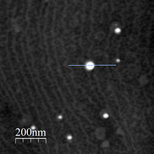
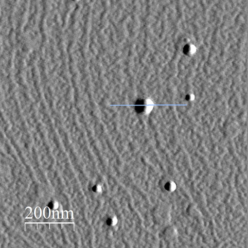
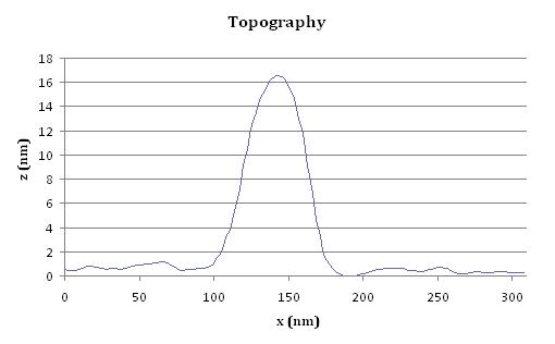
In practice however feedback is never perfect, and there is always some delay between measuring a change from the setpoint and restoring it by adjusting the scanning height. In tapping mode for example this can be measured by the difference between the instantaneous amplitude of oscillation and the amplitude setpoint. This is known as the amplitude error signal, and highlights changes in surface height.
 |
 |
 |
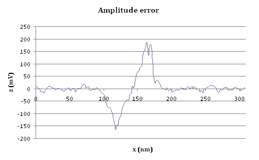 |
| Example images showing the relationship between topography and amplitude error signal. The two line plots demonstrate a slice through the acquired image. | |
The feedback system is affected by three main parameters:
- Setpoint – this is the value of the deflection or amplitude that the feedback circuit attempts to maintain. This is usually set such that the force on the cantilever is small, but the probe remains engaged with the surface.
- Feedback gains – the higher these are set, the faster the feedback system will react. However if the gains are too high then the feedback circuit can become unstable and oscillate, causing high frequency noise in the image.
- Scan rate – scanning the probe over the surface more slowly gives the feedback circuit more time to react and results in better tracking, but this increases the time needed to acquire an image.