
12.6: Multiaxial Creep Testing – Indentation Creep Plastometry
- Page ID
- 7862
")
Indentation creep plastometry is an fairly novel procedure involving use of an indenter, as opposed to conventional uniaxial testing machines. The process has similarities to indentation plastometry, described in the Mechanical Testing TLP. The advantages noted there, arising from the procedure being non-destructive, applicable to small samples of simple shape and offering scope for mapping of properties across a surface, also apply here. Furthermore, while uniaxial creep testing requires a series of tests at different stress levels (and experimental difficulties in maintaining a constant true stress), a single indentation creep experiment allows full characterisation of the creep behaviour (as captured in a constitutive law).
Method
Recess Creation
A spherical indenter is normally used. As with conventional creep testing, it is important to avoid conventional (time independent) plastic deformation. This is particularly an issue in the initial stages, when the contact area would be very low as the indenter penetrated a flat surface, and the stresses correspondingly high. In order to avoid this problem, a (spherical) recess is first created in the sample, matching the indenter. This procedure can be used to ensure that the stresses in the sample never reach the yield stress (at the temperature concerned).
Test Procedure
The selected load is quickly applied and the penetration recorded as a function of time. As with Indentation Plastometry, the core of the procedure is iterative numerical simulation of the test, using the FEM method. A constitutive creep relationship, such as the M-N law, is used in the model, with trial, and then improved, values of the (three) parameters in it, with the goodness of fit parameter (S) between predicted and measured displacement-time curves being used to guide the optimisation. The simulation below shows the outcome of this operation for a particular case (a Ni sample at 750°C, with a 1 kN load, an indenter radius of 2 mm and an initial recess depth of 1 mm, with a 2 mm radius of curvature). The evolving von Mises stress and strain fields are shown, together with measured and modelled displacement-time plots, with the optimised M-N parameter set
Predicted and mesured curves agree quite well - the value of S is 10-3.2, which is acceptably close to zero. The parameter set that gave this level of agreement is shown below:
| Cexp(-Q/RT) / Pa-n s-(m+1) | n | m |
|---|---|---|
| 4.3 10-8 | 2.46 | -0.65 |
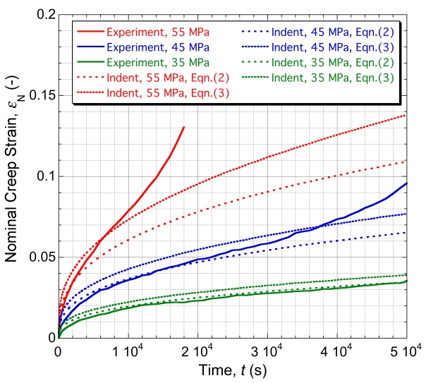
Graph showing how our predictions compare with the experimental data for uniaxial tensile creep testing
Using this parameter set, a prediction can be made (using the M-N law directly, with no need for FEM simulation), of the outcome of uniaxial testing, with any particular applied stress level. The outcome of such operations is compared with experimental data, for this material and test temperature, in the plot shown here. Two sets of predicted plots are shown for each stress level. The first set corresponds to use of Eqn.(2) on the page "Constitutive Laws for Creep" - ie the standard M-N law. In fact, the experimental data were obtained during testing with a fixed load (constant nominal stress), so the appropriate plots are really those marked in the figure as referring to Eqn.(3), which were obtained using the differential form of the M-N law - ie Eqn.(3) on the page "Constitutive Laws for Creep". It can be seen that the agreement with these plots is good, apart from periods towards the end of the test with the higher applied stress levels, when tertiary” behaviour is seen, probably because the true stress was approaching the yield stress (~65 MPa), so that “plasticity” was stimulated.