Engineering LibreTexts

13.5: Experiment

  • Page ID
    8252
  • \( \newcommand{\vecs}[1]{\overset { \scriptstyle \rightharpoonup} {\mathbf{#1}} } \) \( \newcommand{\vecd}[1]{\overset{-\!-\!\rightharpoonup}{\vphantom{a}\smash {#1}}} \)\(\newcommand{\id}{\mathrm{id}}\) \( \newcommand{\Span}{\mathrm{span}}\) \( \newcommand{\kernel}{\mathrm{null}\,}\) \( \newcommand{\range}{\mathrm{range}\,}\) \( \newcommand{\RealPart}{\mathrm{Re}}\) \( \newcommand{\ImaginaryPart}{\mathrm{Im}}\) \( \newcommand{\Argument}{\mathrm{Arg}}\) \( \newcommand{\norm}[1]{\| #1 \|}\) \( \newcommand{\inner}[2]{\langle #1, #2 \rangle}\) \( \newcommand{\Span}{\mathrm{span}}\) \(\newcommand{\id}{\mathrm{id}}\) \( \newcommand{\Span}{\mathrm{span}}\) \( \newcommand{\kernel}{\mathrm{null}\,}\) \( \newcommand{\range}{\mathrm{range}\,}\) \( \newcommand{\RealPart}{\mathrm{Re}}\) \( \newcommand{\ImaginaryPart}{\mathrm{Im}}\) \( \newcommand{\Argument}{\mathrm{Arg}}\) \( \newcommand{\norm}[1]{\| #1 \|}\) \( \newcommand{\inner}[2]{\langle #1, #2 \rangle}\) \( \newcommand{\Span}{\mathrm{span}}\)\(\newcommand{\AA}{\unicode[.8,0]{x212B}}\)

    In this experiment we investigate photoelasticity, the phenomenon of inducing birefringence in a substance through the application of a stress system.

    We investigate birefringence induced in polycarbonate when subjected to three and four point bending. Three different specimens are investigated: a plain bar, a bar with an edge notch, and a bar with a central hole. This will give us an appreciation of the effects of geometric discontinuities on the stress state. Some calculations will then be made using the Stress-Optic Law.

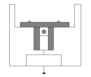
    Simple apparatus is used to deform the polycarbonate specimens. The apparatus comprises an aluminium base fitted with two cylindrical stops and a central groove into which a brass slide may be slotted depending on the stress-state to be applied. For three point bending a slide with a single point is used and for four point bending a slide with two well-separated points. A screw attached to the base allows the slides to be moved normal to the specimen, which is placed against the two cylindrical stops, subjecting the strip to stress. The apparatus is orientated between crossed polars so that the length of the specimens is in the 45° position, i.e. at 45° to the polariser direction.
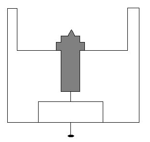
    Diagram of a 3-point bending rig Diagram of a 4-point bending rig

    3-point bending rig

    4-point bending rig


    This page titled 13.5: Experiment is shared under a CC BY-NC-SA license and was authored, remixed, and/or curated by Dissemination of IT for the Promotion of Materials Science (DoITPoMS) via source content that was edited to the style and standards of the LibreTexts platform; a detailed edit history is available upon request.

    • Was this article helpful?