
1.5: Euler-Bernoulli Hypothesis
- Page ID
- 21473

In this section reference is often made to the beam axis. The meaning of the beam axis is intuitive for a prismatic beam with a rectangular cross-section. It is the middle axis. Other terms, such as: neutral axis, bending axis and centroidal axis are also frequently used. They all express the same property that no axial stresses \(\sigma_{xx}\) should develop on the axis under pure bending.
Hypothesis 1: Plan Remains Plane
This is illustrated in Figure (\(\PageIndex{1}\)) showing an arbitrary cross-section of the beam before and after deformation.
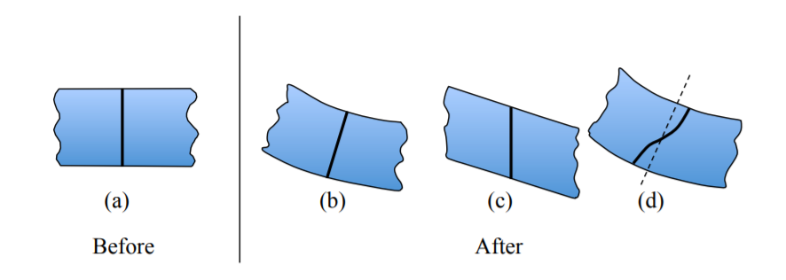
Imagine a straight cut made through the undeformed beam. The plane-remains-plane hypothesis means that all material points on the original cut align also on a plane in the deformed beam. The cases (b) and (c) obey the hypothesis but the warped section (d) violates it.
Hypothesis 2: Normal Remains Normal
If the initial cut were made at right angle of the undeformed beam axis as in Figure (\(\PageIndex{2}\)(a)), it should remain normal to the deformed axis, see Figure (\(\PageIndex{2}\)(b)).
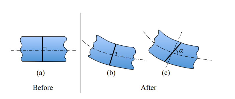
In the sketch on Figure (\(\PageIndex{2}\)(c)) the hypothesis is violated when the angle \(\alpha \neq 90^{\circ}\).
The Euler-Bernoulli hypothesis gives rise to an elegant theory of infinitesimal strains in beams with arbitrary cross-sections and loading in two out-of-plane directions. The interested reader is referred to several monographs with a detailed treatment of the subject, of bi-axial loading of beams. The present set of notes on beams is developed under the assumption of planar deformation. This means that the beam axis motion is restricted only to one plane.
Mathematically, the Hypothesis 1 is satisfied when the u-component of the displacement vector is a linear function of \(z\).
\[u(z) = u^{\circ} - \theta z \text{ at any x} \label{2.35}\]
The constant first term, \(u^{\circ}\) is the displacement of the beam axis (due to axial force). The second term is due to bending alone, Figure (\(\PageIndex{3}\)).
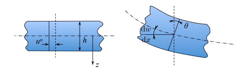
The second Euler-Bernoulli hypothesis is satisfied if the rotation of the deformed crosssection \(\theta\) is equal to the local slope of the bent middle axis \(\frac{ d w}{ d x}\)
\[\theta = \frac{ d w}{ d x} \label{2.36}\]
Eliminating the rotation angle θ between equations \ref{2.35} and \ref{2.36} yields
\[u(x, z) = u^{\circ} - \frac{ d w}{ d x}z \label{2.37}\]
It can be seen from Figure (\(\PageIndex{3}\)) that the displacement at the bottom (tensile) side of the beam is negative, which explains the minus sign in the second term of Equations \ref{2.36} and \ref{2.37}.
Hypothesis 3
The cross-sectional shape and size of the beam remain unchanged. This means that the vertical component of the displacement vector does not depend on the \(z\)-coordinate. All points of the cross-section move by the same amount.
\[w = w(x) \label{2.38}\]
In the case of planar deformation, which covers most of the practical cases of the beam response, the \(y\)-component of the displacement vector vanishes
\[v = 0\]
We are now in the position to calculate all components of the strain tensor from Equation (1.2.10)
\[\epsilon_{xx} = \frac{ d u_{x}}{ d x} = \frac{ d u}{ d x}\]
\[\epsilon_{zz} = \frac{ d u_{y}}{ d y} = \frac{ d v}{ d y} = 0 \text{ on account of } \ref{2.42}\]
\[\epsilon_{zz} = \frac{ d u_{zz}}{ d z} = \frac{ d w(x)}{ d z} = 0 \text{ from } \ref{2.38}\]
\[\epsilon_{xy} = \frac{1}{2} \left(\frac{ d u_{x}}{ d y} + \frac{ d u_y}{ d x} \right) = 0 \text{ from } \ref{2.37} \text{ and } \ref{2.42}\]
\[\epsilon_{yz} = \frac{1}{2} \left(\frac{ d u_{y}}{ d z} + \frac{ d u_z}{ d y} \right) = \frac{1}{2} \left(\frac{ d v}{ d z} + \frac{ d w}{ d y} \right) = 0 \]
\[\begin{align} \epsilon_{zx} & = \frac{1}{2} \left(\frac{ d u_{z}}{ d x} + \frac{ d u_x}{ d z} \right) = \frac{1}{2} \left(\frac{ d w}{ d x} + \frac{ d u}{ d z} \right) \\ & = \frac{1}{2} \left(\frac{ d w}{ d x} - \frac{ d w}{ d x} \right) = 0 \nonumber \end{align}\]
It is seen that all components of the strain tensor vanish except the one in the direction of beam axis.
Note that \(\epsilon_{xx}\) is the only component of the strain tensor in the elementary beam theory. Therefore the subscript “\(xx\)” can be dropped and, unless specified otherwise \(\epsilon_{xx} = \epsilon\). Introducing Equation \ref{2.37} into Equation \ref{2.38} one gets
\[\epsilon (x, z) = \frac{ d u^{\circ}(x)}{ d x} - \frac{ d ^2w(x)}{ d x^2}z\]
The first term represents the strain arising from a uniform extension of the entire cross-section
\[\epsilon^{\circ}(x) = \frac{ d u^{\circ}(x)}{ d x} \label{2.42}\]
The second term adds a contribution of bending. Introducing the definition of the curvature of the beam axis
\[\kappa \buildrel \rm {def} \over{=} −\frac{ d ^2w(x)}{ d x^2},\]
the expression for strain can be put in the final form:
\[\epsilon(x, z) = \epsilon^{\circ}(x) + z\kappa\]
Mathematically, the curvature is defined as a gradient of the slope of a curve. The minus sign in Equation (1.3.4) follows from the rigorous description of the curvature of a line in the assumed coordinate system. Physically, it assumes that strains on the tensile side of the beam are positive. A quite different interpretation of the Euler-Bernoulli hypothesis is offered by considering a two-term expansion of the exact strain profile in the Taylor series around the point
\[\epsilon(x, z) = \epsilon(x, z) = |_{z=0} + \left. \frac{ d {\epsilon}}{ d z}\right|_{z=0} z + \left. \frac{1}{2}\frac{ d ^2 \epsilon} { d z^2}\right|_{z=0} z^2 + \ldots\]
Taking only the first two terms is a good engineering approximation but leads to some internal inconsistencies of the elementary beam theory. These inconsistencies will be explained in the two subsequent chapters.