6.5: Sandwich Plates
- Page ID
- 21508
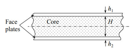
Sandwich plates are composed of face sheets and a lightweight core, Figure (\(\PageIndex{1}\)).

The core is transmitting shear stresses while the face plates are working mostly in tension or compression. Typical materials for a core are polyuritine foam, Aluminum foam, aluminum or nomex honeycombs, polymeric material of various kinds etc. In many steel structures, there is a discrete core made of corrugated sheets welded stiffeners of different topologies or truss structures. Pictures of some typical core materials and sandwich sets are shown in Figure (6.6.1).
In order to determine the bending and axial stiffness of the sandwich plate, we must revisit the definition of bending moment. For cylindrical bending,
\[M_{xx} = \int \sigma z dz = \int_{-\frac{H}{2}}^{\frac{H}{2}} \sigma_cz dz + \sigma_f hH \label{7.48a}\]
\[N_{xx} = \int \sigma dz = \int_{-\frac{H}{2}}^{\frac{H}{2}} \sigma_c dz + 2\sigma_f h \label{7.48b}\]
The Young’s modulus of the core material is usually two orders of magnitude smaller than that of the face plates, so \(\sigma_f \gg \sigma_c\). Neglecting the first term in Equation \ref{7.48a} - \ref{7.48b} and extending the above definitions to plates, the bending moments and axial forces are
\[M_{\alpha \beta} = \sigma_{\alpha \beta}hH \]
\[N_{\alpha \beta} = 2\sigma_{\alpha \beta}h \]
where \(\sigma_{\alpha \beta}\) is related to the face plate strain by the plane stress elasticity law, Equations (3.6.1- 3.6.5). The Love-Kirchhoff hypothesis is still valid so the strains in the face plates are
\[\epsilon_{\alpha \beta} = \epsilon_{\alpha \beta}^{\circ} \pm \frac{H}{2} \kappa_{\alpha \beta}\]
where the “\(\pm\)” sign apply to the tensile and compressive side of the panel. The resulting moment-curvature relations become
\[M_{\alpha \beta} = D_s[(1 − \nu)\kappa_{\alpha \beta} + \nu\kappa_{\gamma \gamma}\delta_{\alpha \beta}] \]
\[N_{\alpha \beta} = C_s[(1 − \nu) \epsilon_{\alpha \beta}^{\circ} + ν\epsilon_{\gamma\gamma} \delta_{\alpha \beta}] \]
where the bending and axial rigidities of the sandwich plates are
\[D_s = \frac{EhH^2}{(1 − \nu^2)}; \quad C_s = \frac{EhH}{1 − \nu^2} \label{7.52}\]
Now, there is more room for the optimum design, because instead of a thickness of a monolithic plate, we have two geometrical parameter to play with. Replacing the bending rigidity \(D\) of the monolithic plate by Equation \ref{7.52}, the bending stiffness of the circular sandwich plate become
\[K_s = 222E \frac{hH^2}{R^2} \]
Assuming the mass density of the core to be two orders of magnitude smaller than the face plate, the total wight of the sandwich plate is
\[W_s = \pi R^2 2h\rho \]
Then, the formula for the bending stiffness per unit weight is
\[\bar{K}_s = 35 \frac{E}{\rho}\frac{H^2}{R^4} \left[\frac{N}{mKg}\right] \]
Two observations can be made. First, \(K_s\) is independent on the thickness of face-plates. Secondly, the stiffness per unit weight increases parabolically with the core thickness \(H\). Does it mean that one can make \(K_s\) as large as desired by increasing \(H\)? This is too good to be true. With increasing \(H\), the sandwich plate may fail in either of the three failure modes:
- Yielding or fracture of face plate on the tensile side;
- Face plate buckling on the compressive side;
- Delamination due to excessive shear.
None of these failure modes are present in monolithic plates. It can be concluded that sandwich plates bring substantial improvements in the bending stiffness but at the same time introduces new unwanted features. Fracture, buckling and shear stresses will be the subject of subsequent lecture. But even at this point we can say that optimization of sandwich plates are possible by determining the maximum core thickness \(H_{opt}\) slightly less than that causing one of the above failure modes.


