6.8: The Concept of Equivalent Thickness
- Page ID
- 21752

Densely spaced and weak stiffeners follow the deflection line of the plate to which they are attached. The main load-resisting mechanism is plate bending with an additional contribution of stiffeners. The solution for the plate is still valid but the plate thickness must be increased to form an equivalent thickness \(h_{eq}\). In plate bending problem the equivalence should be based on equal moment of inertia of two structures, Figure (\(\PageIndex{1}\)).
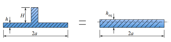
The integrated beam/stiffener system is bending about the common bending axis. The equivalent plate is bending about the middle plane axis. The bending axis of any beam is defined by vanishing the first moment of inertia of the cross-section
\[Q = \int_{A} z dA = 0 \]
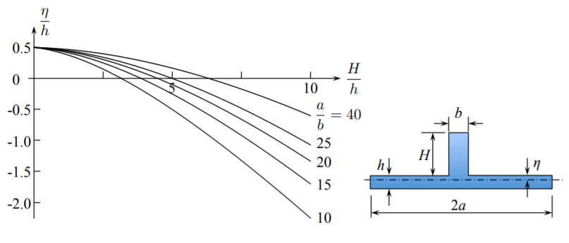
For simplicity, the flat bar stiffener is considered. The position of the neutral axis, normalized with respect to the plate thickness, is related to the remaining parameters of the problem by
\[\frac{\eta}{h} = \frac{1}{2} \frac{1 - \frac{b}{a} \left( \frac{H}{h}\right)^2}{1 + \frac{b}{a} \left( \frac{H}{h}\right)}\]
The plot of the function \(\eta/h\) versus the normalized hight of the stiffener \(H/h\) for several values of the plate-to-stiffener aspect ratio \(a/b\) is shown in Figure (\(\PageIndex{2}\)). In the limiting case of no stiffener, \(H = 0\) and the position of the neutral axis is at the middle axis of the plate.
The moment of inertia of the plate/beam combination and the equivalent plate are, respectively
\[I = \frac{2a}{3} \left[(h^3 − 3h^2 \eta + 3h\eta^2) + \frac{b}{2a} (H^3 + 3H^2\eta + 3H\eta^2) \right]\]
\[I_{eq} = \frac{2a}{12} h^3_{eq} \]
By equating the respective moments of inertia, the equivalent plate thickness, normalized by the thickness of the un-stiffened plate is
\[\left( \frac{h_{eq}}{h}\right)^3 = 4 \left\{ \left[ 1 - 3\eta + 3\left( \frac{\eta}{h}\right)^2\right] + \frac{b}{2a} \left[ \left( \frac{H}{h}\right)^2 + 3 \left( \frac{H}{h}\right)^2 \frac{\eta}{h} + 3 \frac{H}{h}\left( \frac{\eta}{h}\right)^2\right]\right\} \label{7.69}\]
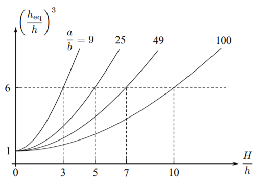
The plot of \(h_{eq}/h\) versus \(H/h\) for several values of the \(a/b\) ratios is given in Figure (\(\PageIndex{3}\)).
The growth of plate stiffness, according to Equation \ref{7.69}, is parabolic with respect to \(\frac{H}{h}\). At the same time the increase in weight (volume) of the orthogonally stiffened plate is linear
\[\frac{V_{eq}}{V} = 1 + \frac{b}{a}\frac{H}{h} \]
Therefore the stiffness per unit weight will still be an increasing function of the height of the stiffeners.
The next question is what should be the height \(H\) and spacing of stiffeners to fall under the category (c) of light stiffeners. This question can be answered by explaining the concept of the shear lag.