
2.5: Live Load Reduction
- Page ID
- 42949

Most codes and standards allow for reduction in live loads when designing large floor systems, since it is very unlikely that such systems will always support the estimated maximum live loads at every instance. Section 4.7.3 of ASCE 7-16 permits a reduction of live loads for members that have an influence area of \(A_{I} \geq 37.2 \mathrm{m}^{2}\left(400 \mathrm{ft}^{2}\right)\). The influence area is the product of the tributary area and the live load element factor. The ASCE 7-16 equations for determining the reduced live load based on the influence area are as follows: \[\begin{array}{l}
L=L_{0}\left(0.25+\frac{15}{\sqrt{K_{L L} A_{T}}}\right)(\mathrm{FPS} \text { units }) \\
L=L_{0}\left(0.25+\frac{4.57}{\sqrt{K_{H} A T}}\right) \quad(\mathrm{SI} \text { units })
\end{array}\]
where
\(L\) = reduced design live load per \(\mathrm{ft}^{2}\) (or \(\mathrm{m}^{2}\)).
\(\geq 0.50 L_{o}\) for structural members supporting one floor (e.g. beams, girders, slabs, etc.).
\(\geq 0.40 L_{o}\) for structural members supporting two or more floors (e.g. columns, etc.).
No reduction is permitted for floor live loads greater than \(4.79 \mathrm{kN} / \mathrm{m}^{2}\left(100 \mathrm{lb} / \mathrm{ft}^{2}\right)\) or for floors of public assembly, such as stadiums, auditoriums, movie theaters, etc., as there is a greater possibility of such floors being overloaded or used as car garages.
ASCE 7-16).
\(A_{T}\) = tributary area of member in \(\mathrm{ft}^{2}\) (or \(\mathrm{m}^{2}\)).
ASCE 7-16).
\(A_{T}\) = \(K_{L L} A_{T}\) = influence area.
\(Table 2.14\). Live load element factor.
|
Building Element |
KLL |
|
Interior columns and exterior columns without cantilever slabs |
4 |
|
Exterior columns with cantilever slabs |
3 |
|
Corner columns with cantilever slabs |
2 |
|
Interior beams and edge beams without cantilever slabs |
2 |
|
All other members, including panels in two-way slabs |
1 |
Example 2.7
A four-story school building used for classrooms has its columns spaced as shown in Figure 2.10. The flat roof loading of the structure is estimated to be \(25 \mathrm{lb} / \mathrm{ft}^{2}\). Determine the reduced live load supported by an interior column at the ground level.
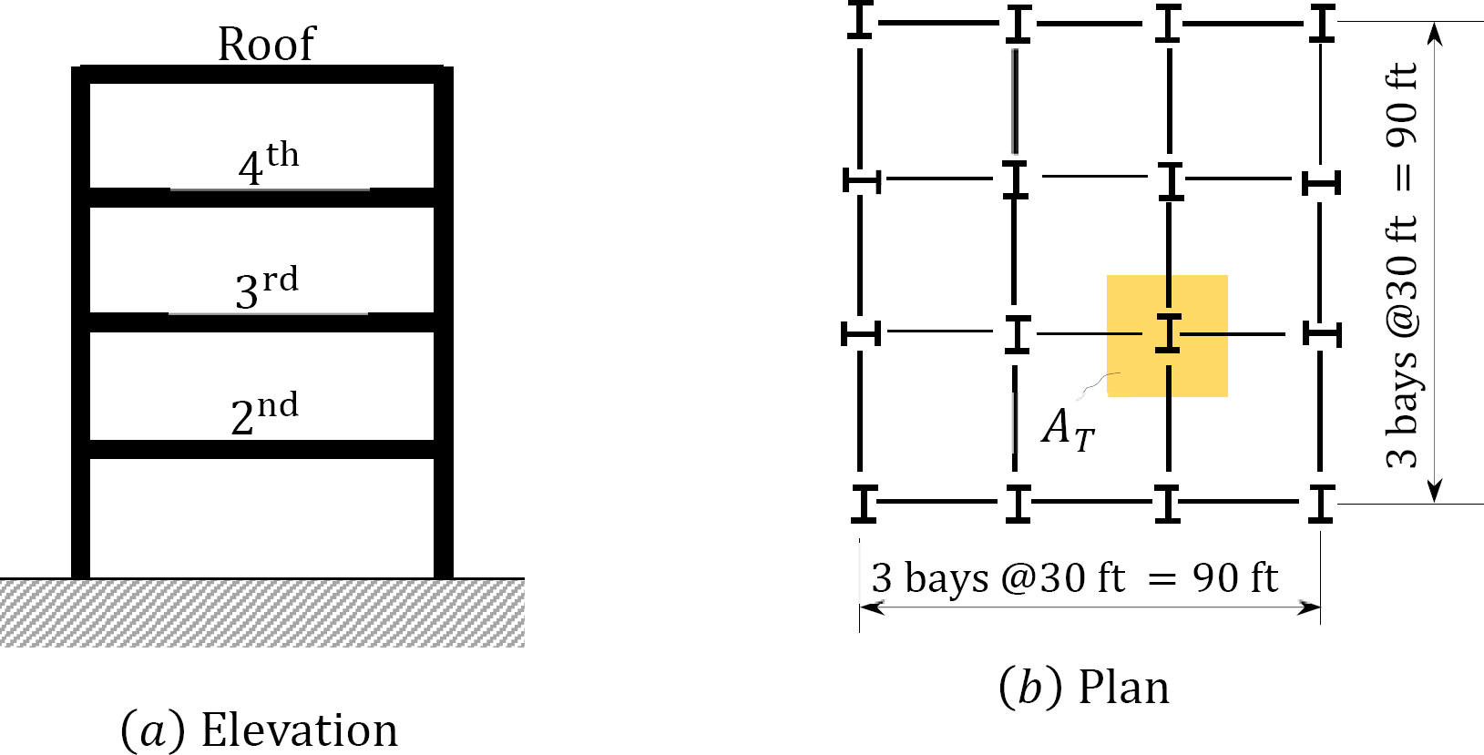
\(Fig. 2.10\). A four – story schol building.
Solution
Any interior column at the ground level supports the roof load and the live loads on the second, third, and fourth floors.
The tributary area of an interior column is \(A_{T}=(30 \mathrm{ft})(30 \mathrm{ft})=900 \mathrm{ft}^{2}\)
The roof live load is \(F_{R}=\left(25 \mathrm{lb} / \mathrm{ft}^{2}\right)\left(900 \mathrm{ft}^{2}\right)=22,500 \mathrm{lb}=22.5 \mathrm{k}\)
For the floor live loads, use the ASCE 7-16 equations to check for the possibility of a reduction.
\(L_{o}=40 \mathrm{Ib} / \mathrm{ft}^{2}\) (from Table 4.1 in ASCE 7-16).
If the interior column \(K_{L L}=4\), then the influence area \(A_{1}=K_{L L} A_{T}=(4)\left(900 \mathrm{ft}^{2}\right)=3600 \mathrm{ft}^{2}\).
Since \(3600 \mathrm{ft}^{2}>400 \mathrm{ft}\), the live load can be reduced using equation 2.14, as follows:
\(L=L_{0}\left(0.25+\frac{15}{\sqrt{K_{L L} A_{T}}}\right)=40\left(0.25+\frac{15}{\sqrt{3600}}\right)=20 \mathrm{lb} / \mathrm{ft}^{2}\)
According to Table 4.1 in ASCE 7-16, the reduced load as a fraction of the unreduced floor live load for a classroom is \(\left(\frac{20}{40}\right)=0.50>0.4\) Thus, the reduced floor live load is as follows:
\(F_{F}=\left(20 \mathrm{lb} / \mathrm{ft}^{2}\right)\left(200 \mathrm{ft}^{2}\right)=18,000 \mathrm{lb}=18 \mathrm{k}\)
The total load supported by the interior column at the ground level is as follows:
\(F_{\text {Tota} /}=22.5 \mathrm{k}+3(18 \mathrm{k})=76.5 \mathrm{k}\)
Chapter Summary
Structural loads and loading systems: Structural elements are designed for the worst possible load combinations. Some of the loads that could act on a structure are briefly defined below.
Dead loads: These are loads of a constant magnitude in a structure. They include the weight of structure and the loads that are permanently attached to the structure.
Live loads: These are loads of varying magnitudes and positions. They include moveable loads and loads due to occupancy.
Impact loads: Impact loads are sudden or rapid loads applied on a structure over a relatively short period of time compared with other structural loads.
Rain loads: These are loads due to accumulation of water on a roof top after a rainstorm.
Wind loads: These are loads due to wind pressure exerted on structures.
Snow loads: These are loads exerted on a structure by accumulated snow on a rooftop.
Earthquake loads: These are loads exerted on a structure by the ground motion caused by seismic forces.
Hydrostatic and earth pressures: These are loads on retaining structures due to pressures developed by the retained materials. They vary linearly with the height of the walls.
Load combinations: The two building design methods are the Load and Resistance Factor Design method (LRFD) and the Allowable Strength Design method (ASD). Some of the load combinations for these methods are shown below.
LRFD:
1.1.4\(D\)
2.1.2 \(D + 1.6 L+0.5\left(L_{r} \text { or } \mid S \text { or } R\right)\)
3.1.2 \(D+1.6\left(L_{r} \text { or } S \text { or } R\right)+(L \text { or } 0.5 \mathrm{W})\)
4.1.2 \(D+1.0 W+L+0.5\left(L_{r} \text { or } S \text { or } R\right)\)
5.0.9 \(D+1.0 W\)
ASD:
1. \(D\)
2. \(D + L\)
3. \(D+\left(L_{r} \text { or } S \text { or } R\right)\)
4. \(D+0.75 L+0.75\left(L_{r} \text { or } S \text { or } R\right)\)
5. \(D+(0.6 \mathrm{W})\)
References
ACI (2016), Building Code Requirements for Structural Concrete (ACI 318-14), American Concrete Institute.
ASCE (2016), Minimum Design Loads for Buildings and Other Structures, ASCE 7-16, ASCE.
ICC (2012), International Building Code, International Code Council.
Practice Problems
2.1 Determine the maximum factored moment for a roof beam subjected to the following service load moments:
\(M_{D}\) = 40 psf (dead load moment)
\(M_{L_{r}}\) = 36 psf (roof live load moment)
\(M_{S}\) = 16 psf (snow load moment)
2.2 Determine the maximum factored load sustained by a column subjected to the following service loads:
\(P_{D}\) = 500 kips (dead load)
\(P_{L}\) = 280 kips (floor live load)
\(P_{S}\) = 200 kips (snow load)
\(P_{E}\) = ±30 kips (earthquake load)
\(P_{W}\) = ±70 kips (wind load)
2.3 The typical layout of a steel-reinforced concrete composite floor system of a library building is shown in Figure P2.1. Determine the dead load in lb/ft acting on a typical interior beam \(B 1-B 2\) in the second floor. All beams are \(W+2 \times 44\), spaced at 10 ft o.c. The distributed loads on the second floor are as follows:
|
2 in. thick sand-cement screed |
= 0.25 psf |
|
6 in. thick reinforced concrete slab |
= 50 psf |
|
Suspended metal lath and gypsum plaster ceiling |
= 10 psf |
|
Electrical and mechanical services |
= 4 psf |
Typical floor plan
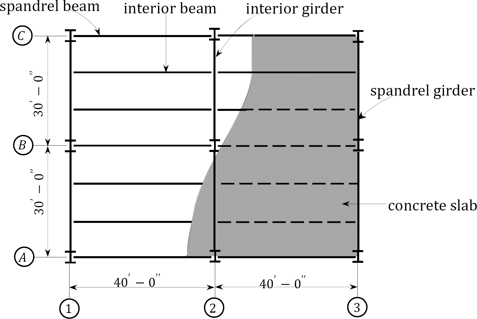
\(Fig. P2.1\). A steel – reinforced concrete composite floor system.
2.5 The second-floor layout of an office facility is shown in Figure P2.1. The floor finishing is similar to that of practice problem 2.3. Determine the total dead load applied to the interior column \(B2\) at the second floor. All beams are \(W 14 \times 75\), and all girders are \(W 18 \times 44\).
2.6 A four-story flat roof hospital building shown in Figure P2.2 has concentrically braced frames as its lateral force resisting system. The weight at each floor level is indicated in the figure. Determine the seismic base shear in kips given the following design data:
\(S_{1}\) = 1.5g
\(S_{s}\) = 0.6g
Site class = D
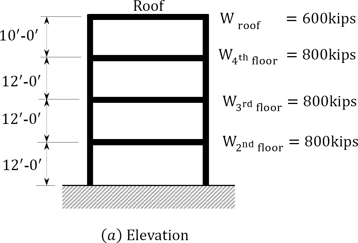
\(Fig. P2.2\). A four – story flat roof building.
2.7 Use ASCE 7-16 to determine the snow load (psf) for the building shown in Figure P2.3. The following data apply to the building:
Ground snow load = 30 psf
Roof is fully exposed with asphalt shingles.
Roof’s slope angle = \(25^{\circ}\)
Open terrain
Occupancy Category I
Unheated structure
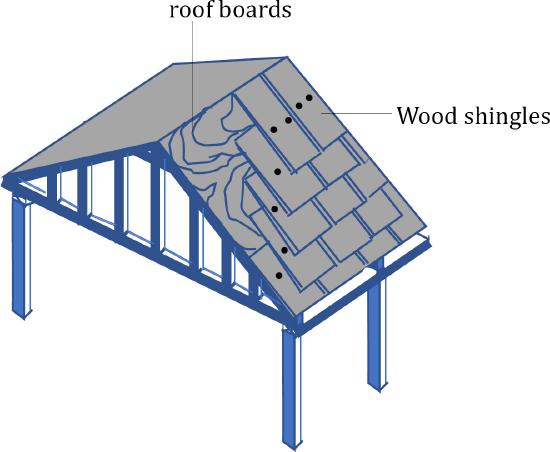
\(Fig. P2.3\). A sample roof.
2.8. In addition to the design snow load computed in practice problem 2.7, the roof of the building in Figure P2.3 is subjected to a dead load of 16 psf (including the weight of a truss, roof board, and asphalt shingle) on the horizontal plane. Determine the uniform load acting on the interior truss, if the trusses are 6ft-0in on center.
2.9 Wind blows at a speed of 90 mph on the enclosed storage facility shown in Figure P2.4. The facility is situated on a flat terrain with an exposure category B. Determine the wind velocity pressure in psf at the eave height of the facility. The topographic factor is Kzt = 1.0.
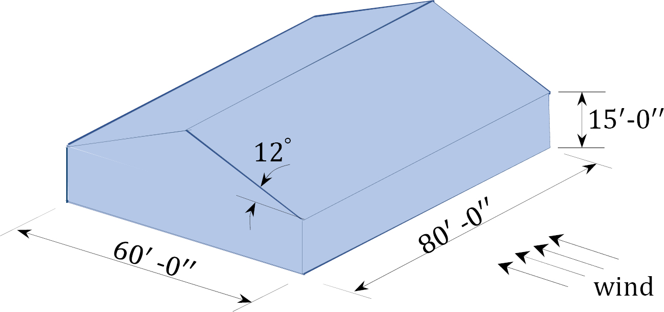
\(Fig. P2.4\). An enclosed storgae facility.