
5.6: Methods of Truss Analysis
- Page ID
- 42966

There are several methods of truss analysis, but the two most common are the method of joint and the method of section (or moment).
5.6.1 Sign Convention
In truss analysis, a negative member axial force implies that the member or the joints at both ends of the member are in compression, while a positive member axial force indicates that the member or the joints at both ends of the member are in tension.
5.6.2 Analysis of Trusses by Method of Joint
This method is based on the principle that if a structural system constitutes a body in equilibrium, then any joint in that system is also in equilibrium and, thus, can be isolated from the entire system and analyzed using the conditions of equilibrium. The method of joint involves successively isolating each joint in a truss system and determining the axial forces in the members meeting at the joint by applying the equations of equilibrium. The detailed procedure for analysis by this method is stated below.
Procedure for Analysis
•Verify the stability and determinacy of the structure. If the truss is stable and determinate, then proceed to the next step.
•Determine the support reactions in the truss.
•Identify the zero-force members in the system. This will immeasurably reduce the computational efforts involved in the analysis.
•Select a joint to analyze. At no instance should there be more than two unknown member forces in the analyzed joint.
•Draw the isolated free-body diagram of the selected joint, and indicate the axial forces in all members meeting at the joint as tensile (i.e. as pulling away from the joint). If this initial assumption is wrong, the determined member axial force will be negative in the analysis, meaning that the member is in compression and not in tension.
•Apply the two equations \(\Sigma F_{X}=0\) and \(\Sigma F_{Y}=0\) to determine the member axial forces.
•Continue the analysis by proceeding to the next joint with two or fewer unknown member forces.
Example 5.2
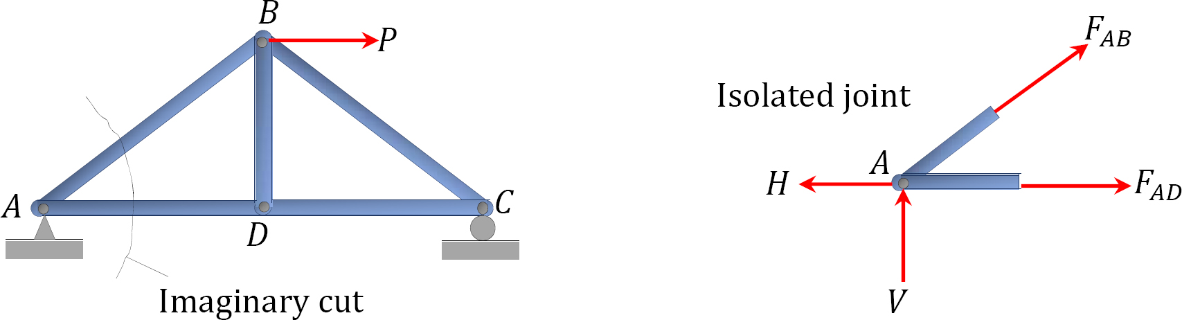
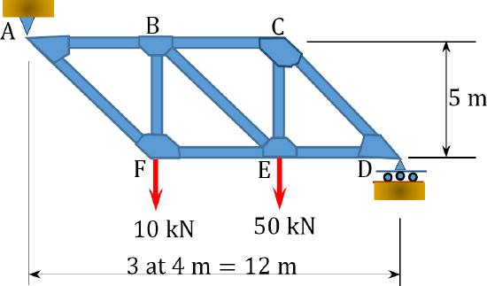
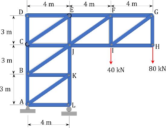
Using the method of joint, determine the axial force in each member of the truss shown in Figure 5.10a.
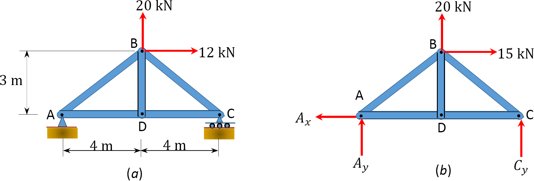
\(Fig. 5.10\). Truss.
Solution
Support reactions. By applying the equations of static equilibrium to the free-body diagram shown in Figure 5.10b, the support reactions can be determined as follows:
\(\begin{array}{ll}
+\curvearrowleft \sum M_{A}=0 \\
20(4)-12(3)+(8) C_{y}=0 \\
C_{y}=-5.5 \mathrm{kN} & C_{y}=5.5 \mathrm{kN} \downarrow \\
+\uparrow \sum F_{y}=0 \\
A_{y}-5.5+20=0 \\
A_{y}=-14.5 \mathrm{kN} & A_{y}=14.5 \mathrm{kN} \downarrow \\
+\rightarrow \sum F_{x}=0 \\
-A_{x}+12=0 \\
A_{x}=12 \mathrm{kN} & A_{x}=12 \mathrm{kN} \leftarrow \\
\end{array}\)
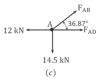
Analysis of joints. The analysis begins with selecting a joint that has two or fewer unknown member forces. The free-body diagram of the truss will show that joints \(A\) and \(B\) satisfy this requirement. To determine the axial forces in members meeting at joint \(A\), first isolate the joint from the truss and indicate the axial forces of members as \(F_{A B}\) and \(F_{A D}\), as shown in Figure 5.10c. The two unknown forces are initially assumed to be tensile (i.e. pulling away from the joint). If this initial assumption is incorrect, the computed values of the axial forces will be negative, signifying compression.
Analysis of joint \(A\).
\(\begin{array}{l}
+\uparrow \sum F_{y}=0 \\
F_{A B} \sin 36.87^{\circ}-14.5=0 \\
F_{A B}=24.17 \\
+\rightarrow \sum F_{x}=0 \\
-12+F_{A D}+F_{A B} \cos 36.87^{\circ}=0 \\
F_{A D}=12-24.17 \cos 36.87^{\circ}=-7.34 \mathrm{kN}
\end{array}\)
After completing the analysis of joint \(A\), joint \(B\) or \(D\) can be analyzed, as there are only two unknown forces.
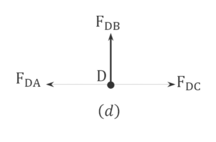
Analysis of joint \(D\).
\(\begin{array}{l}
+\uparrow \sum F_{y}=0 \\
F_{D B}=0 \\
+\rightarrow \sum F_{x}=0 \\
-F_{D A}+F_{D C}=0 \\
F_{D C}=F_{D A}=-7.34 \mathrm{kN}
\end{array}\)
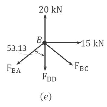
Analysis of joint \(B\).
\(\begin{array}{l}
+\rightarrow \sum F_{x}=0 \\
-F_{B A} \sin 53.13+F_{B C} \sin 53.13+15=0 \\
F_{B C} \sin 53.13=-15+24.17 \sin 53.13= \\
F_{B C}=5.42 \mathrm{kN}
\end{array}\)
5.6.3 Zero Force Members
Complex truss analysis can be greatly simplified by first identifying the “zero force members.” A zero force member is one that is not subjected to any axial load. Sometimes, such members are introduced into the truss system to prevent the buckling and vibration of other members. The truss-member arrangements that result in zero force members are listed as follows:
1.If noncollinearity exists between two members meeting at a joint that is not subjected to any external force, then the two members are zero force members (see Figure 5.11a).
2.If three members meet at a joint with no external force, and two of the members are collinear, the third member is a zero force member (see Figure 5.11b).
3.If two members meet at a joint, and an applied force at the joint is parallel to one member and perpendicular to the other, then the member perpendicular to the applied force is a zero force member (see Figure 5.11c).
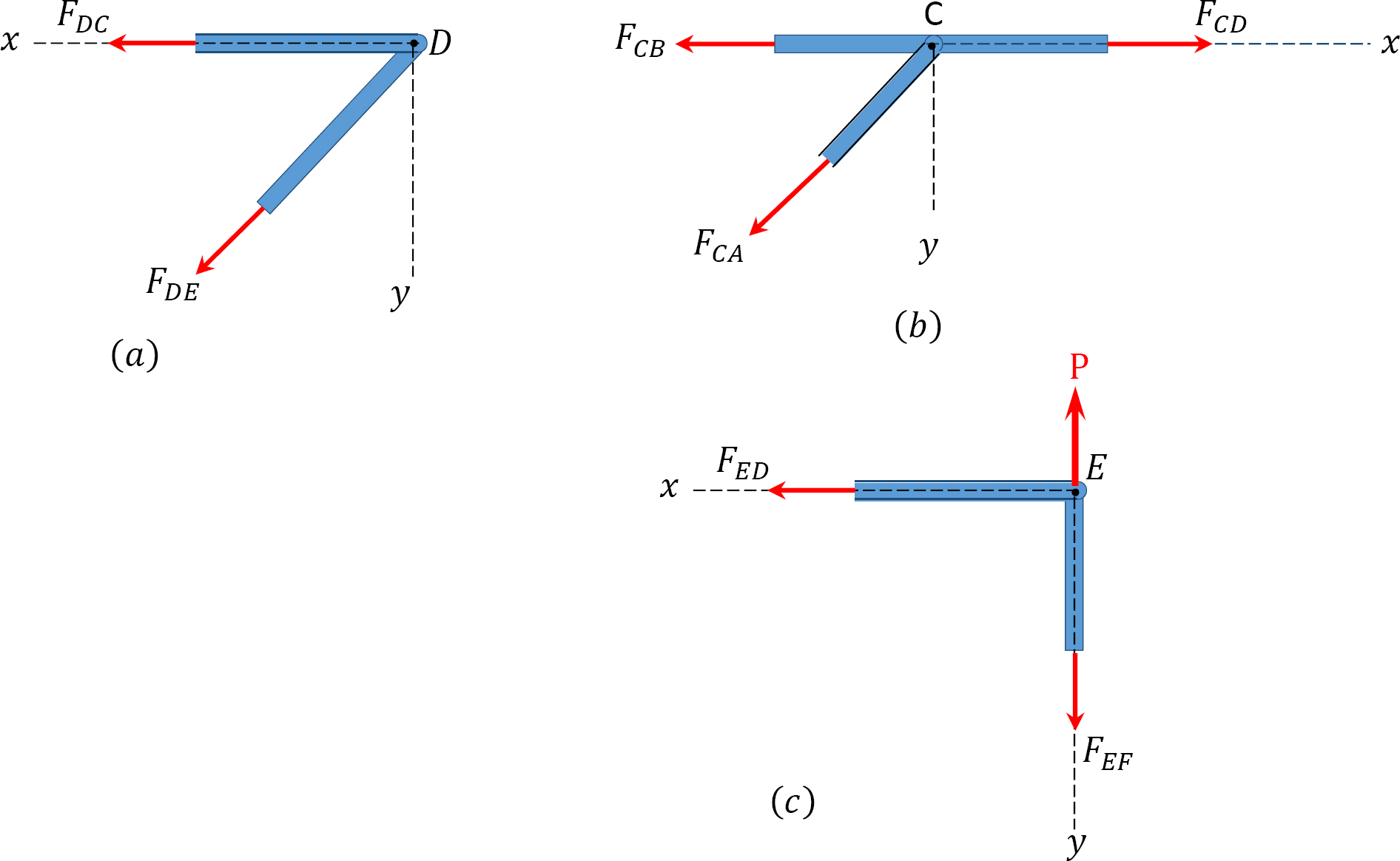
\(Fig. 5.11\). Zero force members.
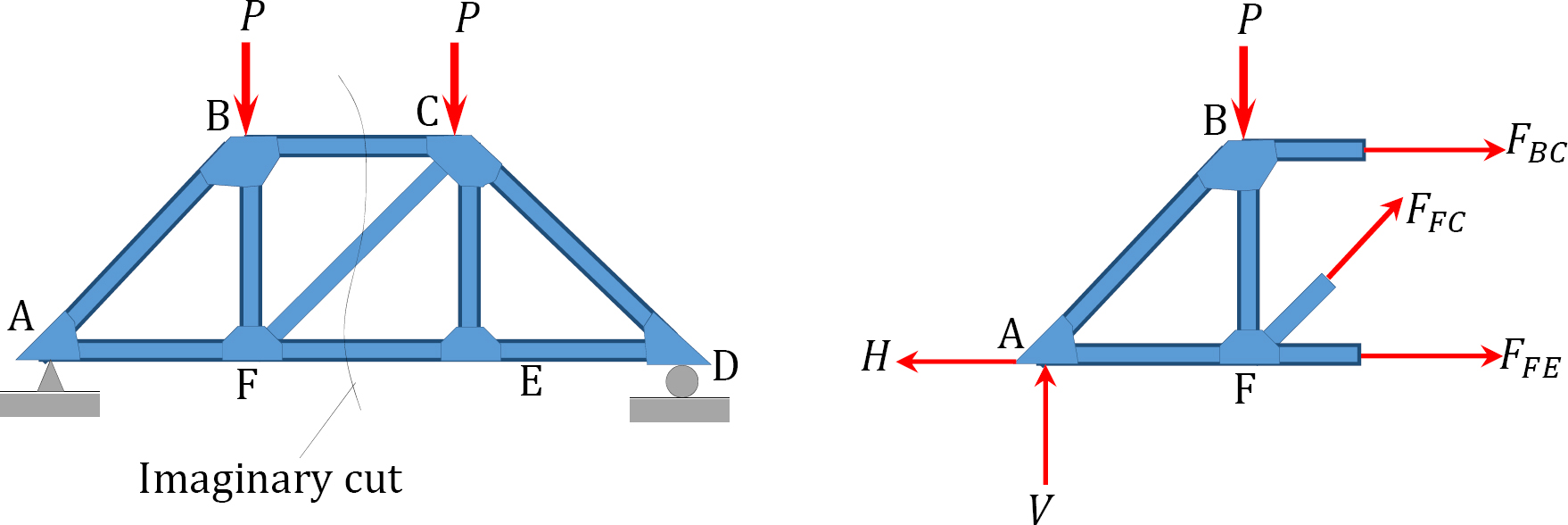
5.6.4 Analysis of Trusses by Method of Section
Sometimes, determining the axial force in specific members of a truss system by the method of joint can be very involving and cumbersome, especially when the system consists of several members. In such instances, using the method of section can be timesaving and, thus, preferable. This method involves passing an imaginary section through the truss so that it divides the system into two parts and cuts through members whose axial forces are desired. Member axial forces are then determined using the conditions of equilibrium. The detailed procedure for analysis by this method is presented below.
Procedure for Analysis of Trusses by Method of Section
•Check the stability and determinacy of the structure. If the truss is stable and determinate, then proceed to the next step.
•Determine the support reactions in the truss.
•Make an imaginary cut through the structure so that it includes the members whose axial forces are desired. The imaginary cut divides the truss into two parts.
•Apply forces to each part of the truss to keep it in equilibrium.
•Select either part of the truss for the determination of member forces.
•Apply the conditions of equilibrium to determine the member axial forces.
Example 5.3
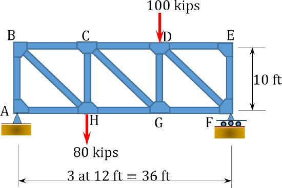
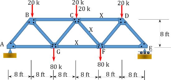
Using the method of section, determine the axial forces in members \(CD\), \(CG\), and \(HG\) of the truss shown in Figure 5.12a.
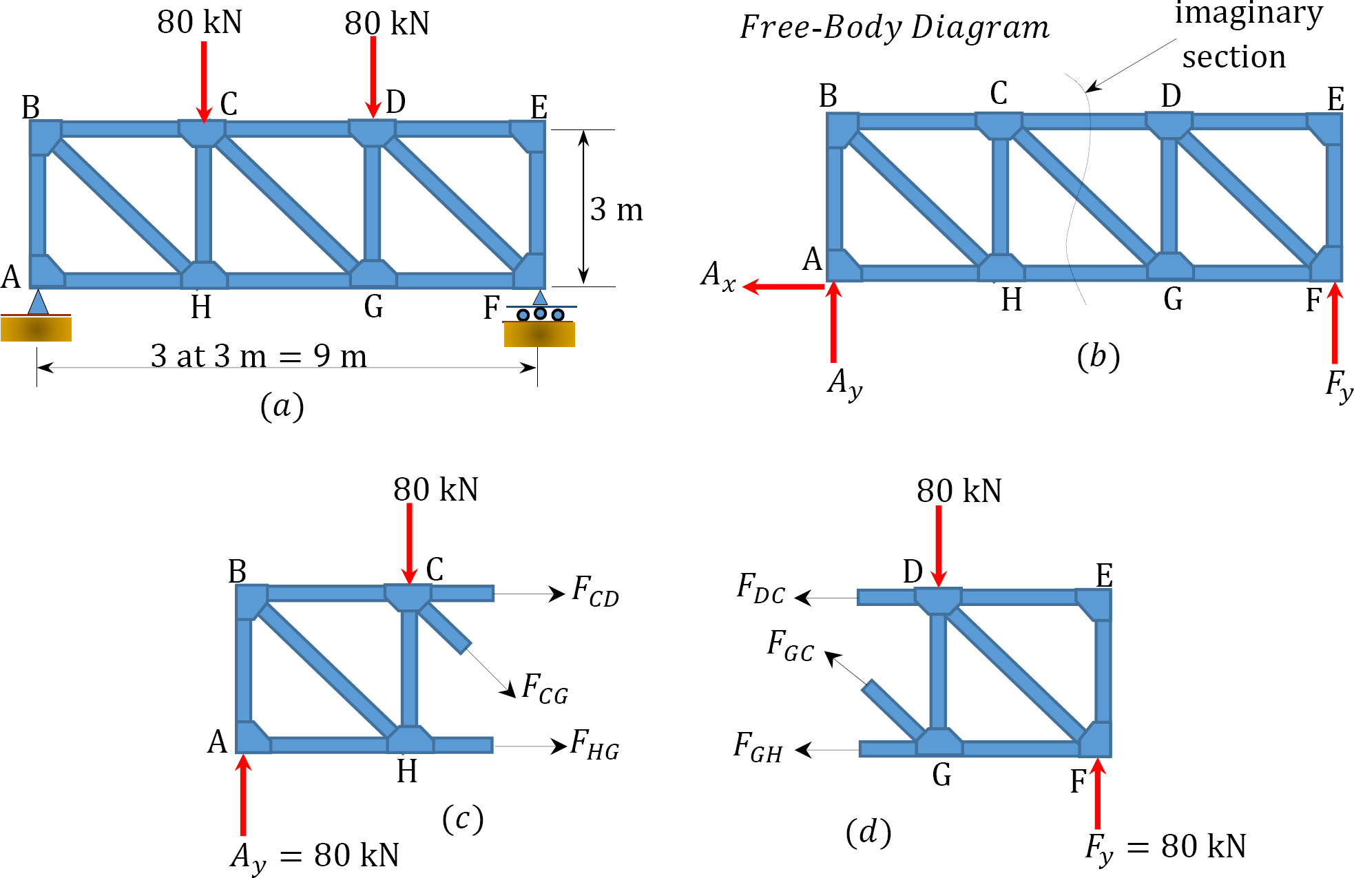
\(Fig. 5.12\). Truss.
Solution
Support reactions. By applying the equations of static equilibrium to the free-body diagram in Figure 5.12b, the support reactions can be determined as follows:
\(\begin{array}{l}
A_{y}=F_{y}=\frac{160}{2}=80 \mathrm{kN} \\
+\rightarrow \Sigma F_{x}=0 \quad A_{x}=0
\end{array}\)
Analysis by method of section. First, an imaginary section is passed through the truss so that it cuts through members \(CD\), \(CG\), and \(HG\) and divides the truss into two parts, as shown in Figure 5.12c and Figure 5.12d. Member forces are all indicated as tensile forces (i.e., pulling away from the joint). If this initial assumption is wrong, the calculated member forces will be negative, showing that they are in compression. Either of the two parts can be used for the analysis. The left-hand part will be used for determining the member forces in this example. By applying the equation of equilibrium to the left-hand segment of the truss, the axial forces in members can be determined as follows:
Axial force in member \(CD\). To determine the axial force in member \(CD\), find a moment about a joint in the truss where only \(CD\) will have a moment about that joint and all other cut members will have no moment. A close examination will show that the joint that meets this requirement is joint \(G\). Thus, taking the moment about \(G\) suggests the following:
\(\begin{array}{l}
+\curvearrowleft \sum M_{G}=0 \\
-80(6)+80(3)-F_{C D}(3)=0 \\
F_{C D}=-80 \mathrm{kN} & 80 \mathrm{kN} (C)
\end{array}\)
Axial force in member \(HG\).
\(\begin{array}{l}
+\curvearrowleft \sum M_{C}=0 \\
-80(3)+F_{H G}(3)=0 \\
F_{H G}=80 \mathrm{kN} & 80 \mathrm{kN} (T)
\end{array}\)
Axial force in member \(CG\). The axial force in member \(CG\) is determined by considering the vertical equilibrium of the left-hand part. Thus,
\(\begin{array}{l}
+\uparrow \sum F_{y}=0 \\
80-80-F_{C G} \cos 45^{\circ}=0 \\
F_{C G}=0
\end{array}\)
Chapter Summary
Internal forces in plane trusses: Trusses are structural systems that consist of straight and slender members connected at their ends. The assumptions in the analysis of plane trusses include the following:
1.Members of trusses are connected at their ends by frictionless pins.
2.Members are straight and are subjected to axial forces.
3.Members’ deformations are small and negligible.
4.Loads in trusses are only applied at their joints.
Members of a truss can be subjected to axial compression or axial tension. Axial compression of members is always considered negative, while axial tension is always considered positive.
Trusses can be externally or internally determinate or indeterminate. Externally determinate trusses are those whose unknown external reactions can be determined using only the equation of static equilibrium. Externally indeterminate trusses are those whose external unknown reaction cannot be determined completely using the equations of equilibrium. To determine the number of unknown reactions in excess of the equation of equilibrium for the indeterminate trusses, additional equations must be formulated based on the compatibility of parts of the system. Internally determinate trusses are those whose members are so arranged that just enough triangular cells are formed to prevent geometrical instability of the system.
The formulation of stability and determinacy in trusses is as follows:
\(\begin{array}{l}
m+r<2 j \quad \text { structure is statically unstable } \\
m+r=2 j \quad \text { structure is determinate } \\
m+r>2 j \quad \text { structure is indeterminate }
\end{array}\)
Methods of analysis of trusses: The two common methods of analysis of trusses are the method of joint and the method of section (or moment).
Method of joint: This method involves isolating each joint of the truss and considering the equilibrium of the joint when determining the member axial force. Two equations used in determining the member axial forces are \(\Sigma F_{X}=0\) and \(\Sigma F_{y}=0\). Joints are isolated consecutively for analysis based on the principle that the number of the unknown member axial forces should never be more than two in the joint under consideration in a plane trust.
Method of section: This method entails passing an imaginary section through the truss to divide it into two sections. The member forces are determined by considering the equilibrium of the part of the truss on either side of the section. This method is advantageous when the axial forces in specific members are required in a truss with several members.
Practice Problems
5.1 Classify the trusses shown in Figure P5.1a through Figure P5.1r.
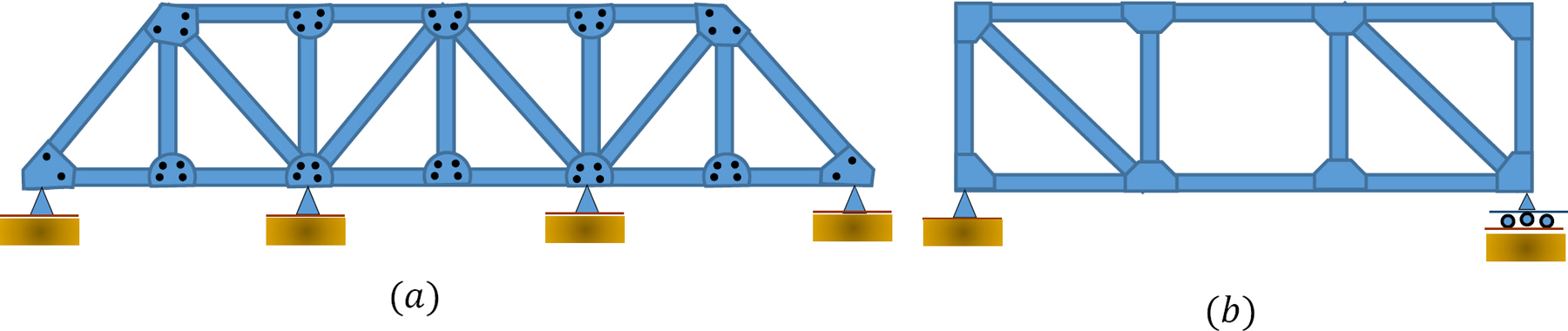
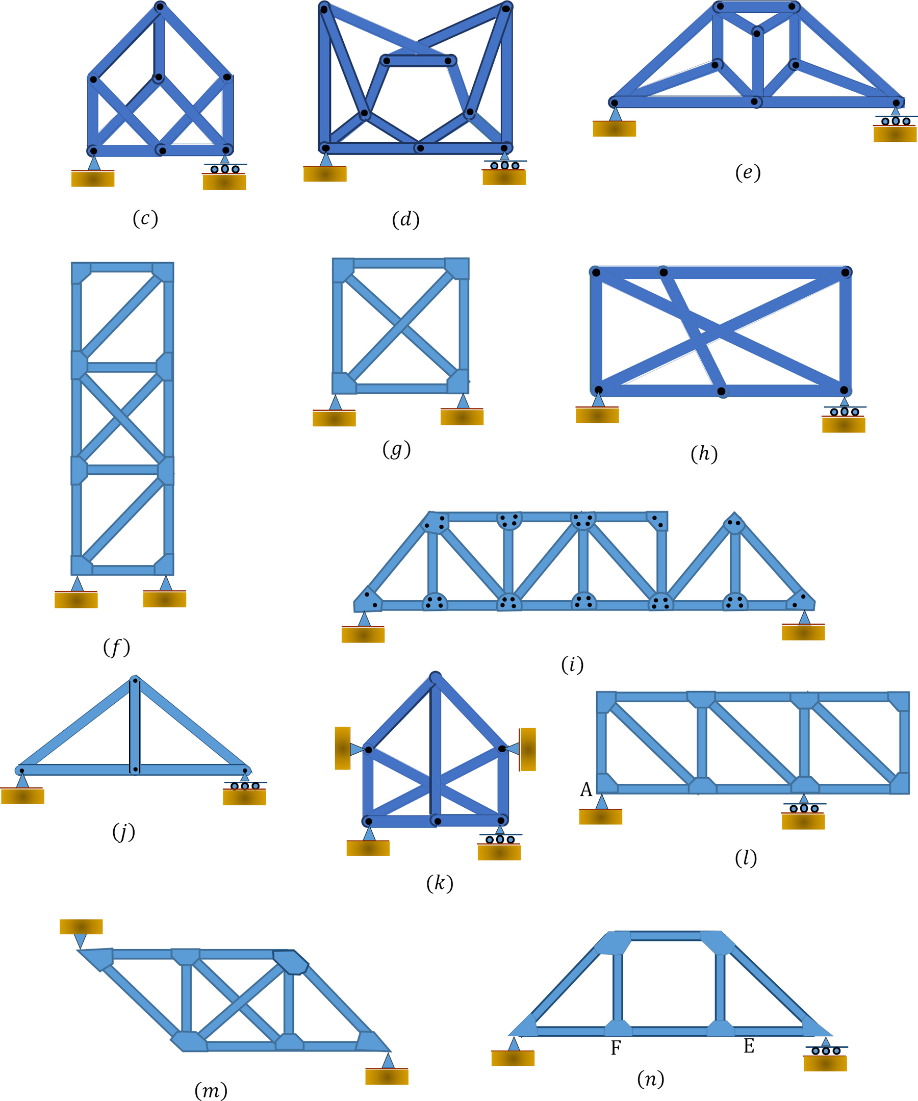
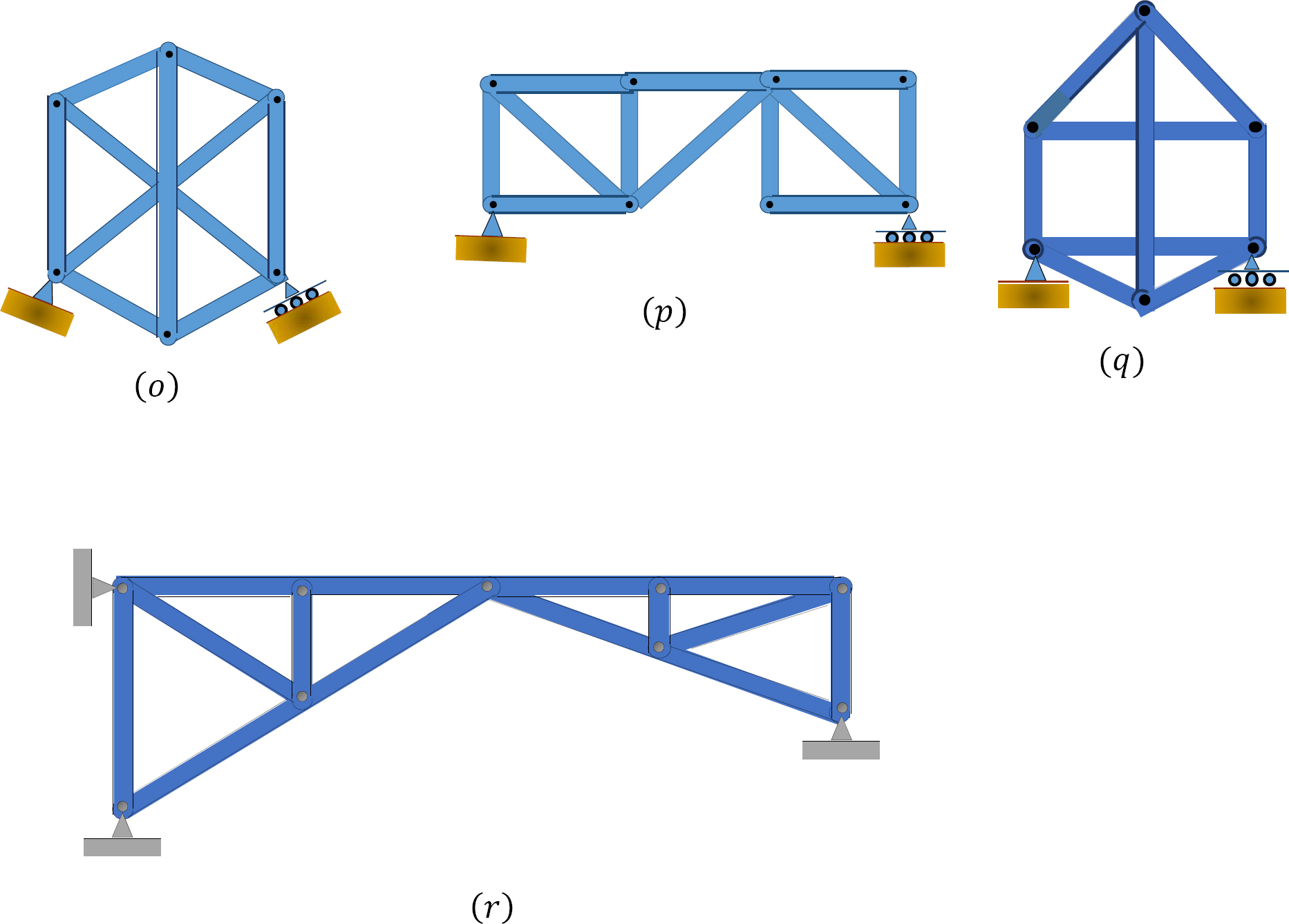
\(Fig. P5.1\). Truss classification.
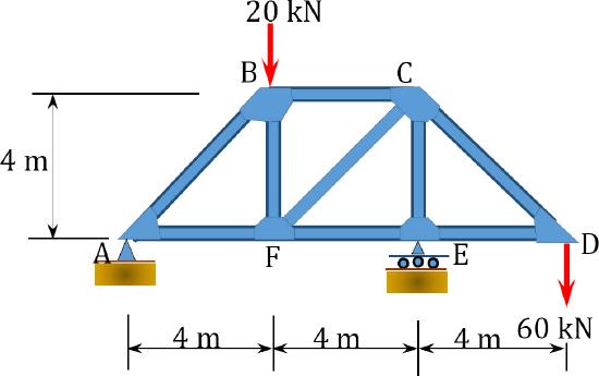
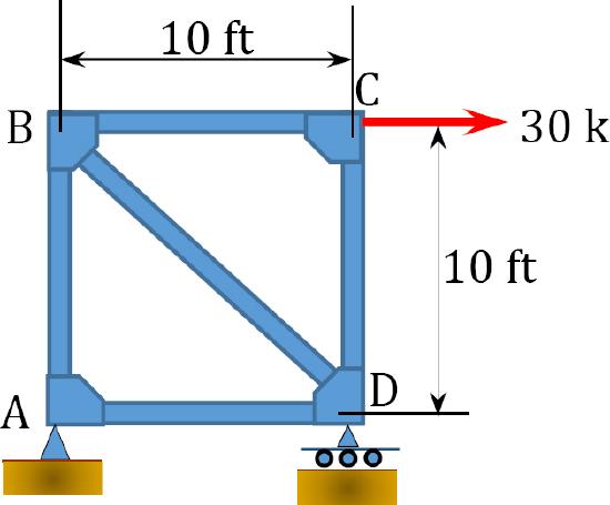
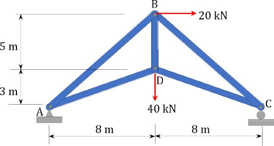
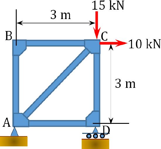
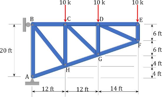
5.2 Determine the force in each member of the trusses shown in Figure P5.2 through Figure P5.12 using the method of joint.
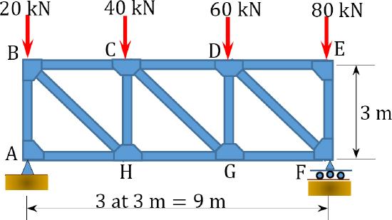
\(Fig. P5.2\). Truss.
\(Fig. P5.3\). Truss.
\(Fig. P5.4\). Truss.
\(Fig. P5.5\). Truss.
\(Fig. P5.6\). Truss.
\(Fig. P5.7\). Truss.
\(Fig. P5.8\). Truss.
\(Fig. P5.9\). Truss.
\(Fig. P5.10\). Truss.
\(Fig. P5.11\). Truss.
\(Fig. 5.12\). Truss.
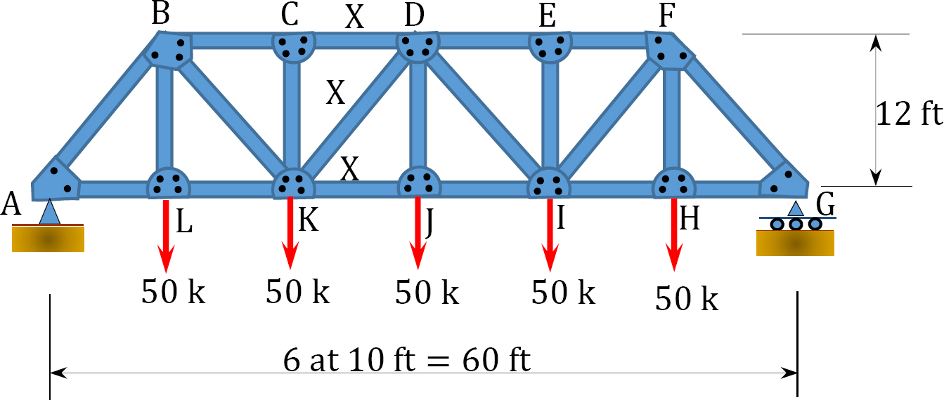
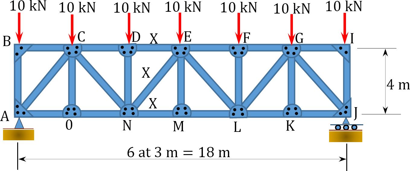
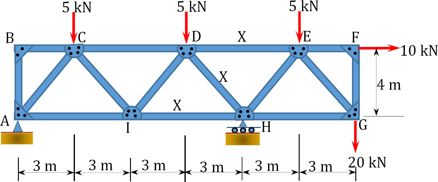
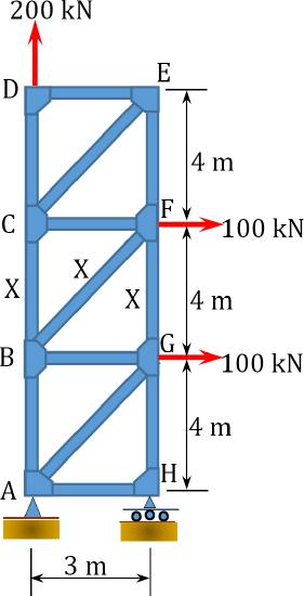
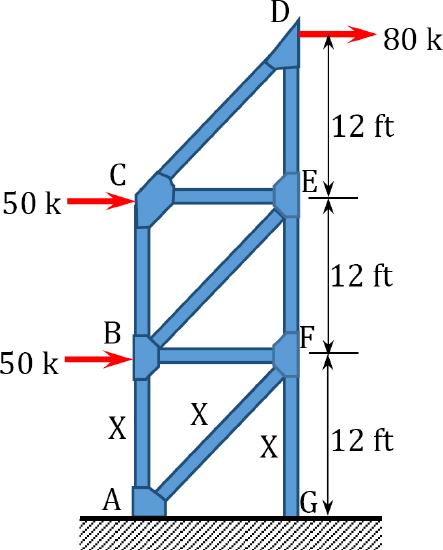
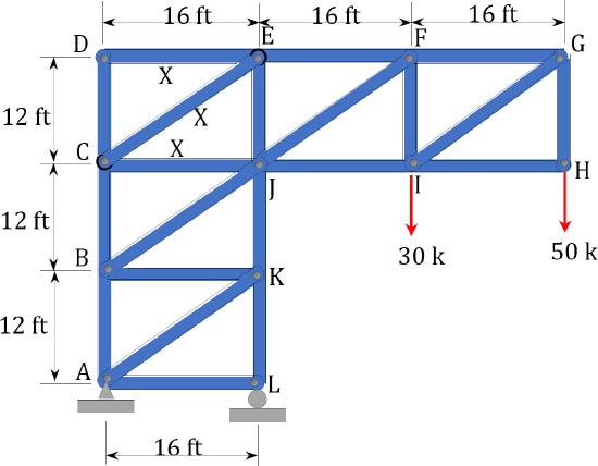
5.3 Using the method of section, determine the forces in the members marked X of the trusses shown in Figure P5.13 through Figure P5.19.
\(Fig. P5.13\). Truss.
\(Fig. P5.14\). Truss.
\(Fig. P5.15\). Truss.
\(Fig. P5.16\). Truss.
\(Fig. P5.17\). Truss.
\(Fig. P5.18\). Truss.
\(Fig. P5.19\). Truss.